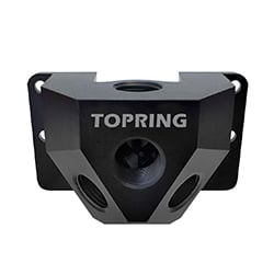
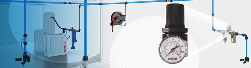
If there is a vast subject to be explored in the field of compressed air, it is that of air preparation. Whether we are talking about air preparation, treatment, or conditioning, we are always talking about the same thing. Whether it is pollution, humidity, or approximate pressure, air should not be used in the raw state (directly from the compressor). In order to work well, and I’m talking about both the efficiency of the tool and the quality of the desired result, you have to “treat” the air to be able to exploit it as a reliable and viable energy source. To do so, we will look at three major aspects:
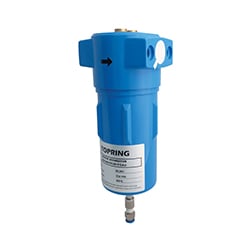
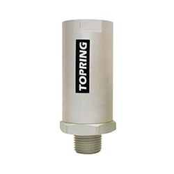
Dust filtration
When compressed air comes out of the compressor in the “raw” state, it is not ready to be used immediately. At this point, the air is compressed, but it is also polluted with a multitude of particles of all kinds:
| Solid Particles | Gases |
|
|
The quantity of these solid or gaseous elements is estimated at +40 million particles per m2 of air in the atmosphere of a normally polluted city! To clean the air, I start by filtering it. It’s like when I make pasta. When I'm done cooking my pasta, I'm going to use a strainer to separate it from the cooking water. The holes are smaller than my pasta, so the water will pass through and my pasta remains in the strainer. The filter works in the same way. This is called mechanical filtration.
What level of filtration to choose
To select the filter cartridge thinness, assess the risk to the tools. Disassembling truck tires do not require as much fineness of air as pulling teeth…
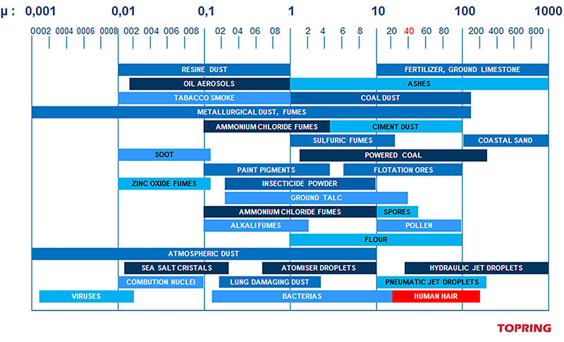
Thus, we will find that there are different levels of filtration on the market (generally ranging from 0.01 to 25 or 30 microns). Of course, the finer the filtration, the more expensive it is… Hence the importance of choosing wisely.
First, estimate the maximum size of acceptable impurities. Be careful, the idea that the filter removes all traces of water is not accurate. If the cartridge can possibly collect some water particles, only the largest ones will remain, often present in a mixture with compressor oil, dust, etc. If the application requires dry air, filtration alone is not enough. We will talk about how to go a little further into air treatment and add other processes later in this article.
The choice of degree of filtration must remain logical… A jackhammer can probably settle for a level of 25 or 30 microns while a smaller or more sensitive tool requires 5 microns.
Sometimes, you must also consider the destination of the tool: filtration for a blow gun depends on the type of surface I blow on (a piece of raw metal vs very thin paper).
When purchasing tools or machines, read the instructions carefully because it is common for manufacturers to indicate the recommended level of filtration. The attached table can help you understand the particle size you are facing and thus allow you to determine the required filtration level.
With regard to submicron filtration, which is finer than a micron, the process used cannot be “mechanical”. It must be of the coalescence type. A principle is used which by capillarity, will retain the finest particles of water and oil and then reconcentrate them to evacuate them.
Where to install filtration elements in a compressed air system
I have often met users who, despite good filtration at the head of the compressed air network, still had problems related to particle filtration. If this is the case for you, know that it is necessary to install a last filter as close as possible to the tool.
When steel piping is oxidized, rust particles come off the inner walls of the pipe. These particles, thrown into the air stream are embedded in the blades of the tool motor.
An aluminum network could save you a lot of trouble since the pipes will not corrode.
In the same vein, I have often heard users tell me that they do not work in a fixed position in their workshop. In this case, installing a filter at each compressed air point of use could be expensive and rarely used! The solution to this type of situation will then be to opt for filters that are also mobile! There are filtration sets on the market mounted on portable chassis. Another option is to install the filter on the tool trolley that follows the user on their workstation. Thus, equipping each employee with their own filter will cost much less than installing one on each air descent!
A good reflex to avoid rising costs is simply to put the filters in the right place. Thus, a painter in an autobody shop needs a submicron filtration (0.01 micron) because of the very high sensitivity of his paints. They can limit this level of filtration to the cabin, where treatment is mandatory. This allows them to invest in equipment calibrated only for their spraying stations (therefore smaller throughput) and not in the entire workshop that does not need such a quality of processing. Our bodybuilder kills two birds with one stone! It saves on cost while ensuring excellent filtration at the most sensitive point of their activity.
Good things to know about filtration
The micron (1µ) is a unit of measure that represents a thousandth of a millimeter (1 mm divided by 1000, which is very small!). The smallest particle visible to the naked eye is 40 microns in size (for example, a human hair can be 20 to 200 microns in diameter).
Filtration remains a crucial element in the design of a compressed air installation but should be considered as part of a more global scheme. To avoid too many air quality problems, step back, starting with the choice of compressor location.
On the other hand, do not forget to regularly purge the filter bowls. Once the tanks are full, the "condensates" (residues of the filtration) are re-injected into the compressed air stream and can quietly harm the network.
Several purge systems or condensate drains perform manual or automatic emptying. Pay attention to the semi-automatic purge, which only works in the absence of pressure. If your network remains under constant pressure, the purge will never work!
As part of maintenance, there are several types of cartridges. On conventional devices, the cartridge can be changed or cleaned (soap and then a good rinse). In all cases, watch the cartridge carefully to avoid a high-pressure loss.
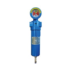
Filters are sometimes fitted with a clogging indicator (called a pressure loss indicator or differential manometer). This device mounted on the filter head measures the pressure difference between the inlet air and the outlet air. If the difference passes a certain level, it is because the cartridge is dirty and must be changed quickly.
See the Topring article for tips on how to maintain a filter.
Skeptics will ask if the result of good filtration justifies its price… My answer to them is that it is not the price that must be considered, but the cost. Be careful not to confuse the two: the results obtained and the problems avoided clearly answer the question. The cost of a well-done filtration is definitely very profitable!
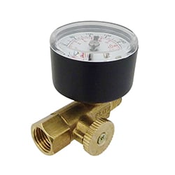
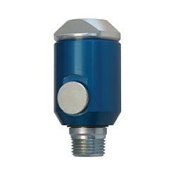
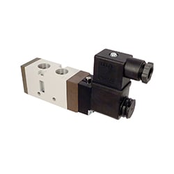
Pressure regulation
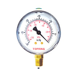
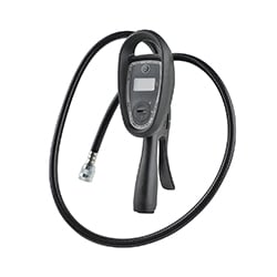
I often hear, "My compressor has over 100 PSI output, it’s good like that!" Looking closer, even if an initial pressure has been preset to compression, reading a manometer or pressure gauge will clearly show irregular and permanent variations in PSI (pounds per square inch). These deviations of the pressure level obviously require a correction in order to maintain a perfect regularity of the pressure and ensure the best supply of air to the tool, whatever it may be. The most common principle is the use of a membrane regulator.
How a membrane regulator works
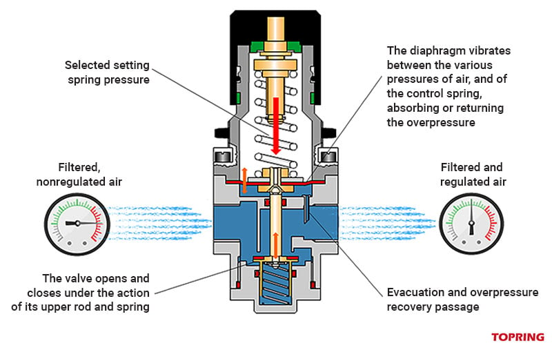
The air passes through the regulator through an air lock whose exit door (the valve) will open more or less according to the pressure (too strong or too weak). The valve is controlled by the said membrane (an axis connects them vertically).
When you choose the right pressure for the tool, you act on an adjustment button on the regulator head. By turning it one way or the other, you compress or relax an internal spring (tension spring). This spring pushes directly on the membrane at the selected pressure (see the needle on the gauge). The membrane forms the ceiling of a small chamber above the air passage. A very small hole (recovery passage) allows, and just before the outlet of the regulator allows compressed air to enter or exit this chamber.
For example, if I set the pressure to 90 PSI and the air coming out of the compressor is 92 PSI, then a small portion of that air will enter the chamber and push the membrane upward (since the membrane is adjusted to 90, 92 versus 90… the membrane lifts!). The valve which is connected to it (by a small axis) will go up a little and thus slow down the passage of air. As a result, the pressure coming out of the regulator will drop.
The system works in both directions (too much pressure or not enough pressure) and the membrane (sometimes called a diaphragm) will suck the excess pressure or push the overpressure from the chamber into the main passage. But we must understand that all this is happening at a very high speed! The diaphragm works a bit like the wings of a hummingbird which are not visible because they beat so fast! The faster the diaphragm vibrates, the more linear the regulation.
Why regulate compressed air
Here are 4 reasons to regulate compressed air.
Protecting the tool mechanism
Regulating the air allows you to protect the mechanism of the tool connected to the line. Manufacturers design their motors with a pressure rating that is the basis for all strength calculations for the various parts. To protect your machines, and your wallet, stick to what is recommended. The most common tools usually require a pressure of 90 PSI. In this case, going over 100 PSI is like going into overdrive...
Improve operational efficiency
Let's take the example of drilling two holes in a piece of metal:
- Take a pneumatic drill and a new drill bit.
- Start a stopwatch at the very moment the tip touches the workpiece and then stop the count the moment it comes out the other side.
- Repeat the operation a second time under the exact same conditions, with the only difference being the pressure of the compressed air, which you change by 7 or 8 PSI.
- The result is obvious: you will notice a time difference of several seconds for the same work!
You will tell me that for one hole, it is not very serious... No, of course, but for a thousand holes... it is more irritating!
Imagine that you are a multinational company that produces millions of cans of soft drinks per day. If the production line loses one second per can, that's hours of lost production and hundreds, even thousands, of cans!
Limiting energy losses
As everyone knows, there are always leaks in compressed air networks. Regulating at the head of the network will limit the volume of leaks. Choose a pressure slightly higher than needed on the main line, up to the peak point at each workstation. For example, stay at 100 PSI on the network and go to 90 PSI at the workstation.
Customize the pressure to the application
Some types of work require a very different control than other applications. Examples include painting, varnishing, blowing, breathing air, etc. For these applications, not regulating means at best a complete failure, and at worst a catastrophic accident!
Where to install the regulator on the air system
For the location of the regulators, follow the same rule as for the filtration. Namely, as close as possible to the workstation. This avoids a possible pressure drop during the distance between the regulator and the machine... Sometimes, the work is done outside the workshop (think of some operations on trucks that are done in the garage yard). In this case, it is probably far from the air point of use. The solution is similar to what you would do for filtration; use a portable regulator in order to connect the tool as close as possible. You can attach the regulator to the tool cart, which will provide the same result. That said, as explained above, a head-end regulator is recommended at the compressor outlet. This allows the air to be regulated in two stages, which is better for the overall operation of the entire system.
Things to remember
- Since the regulator is a rather fragile reading instrument, install it in a place where vibrations are not likely to upset it.
- Place the regulator after a filter in order to protect it from impurities that could damage its mechanism.
- Always check that the pressure gauge is working properly. If it does not work, you will be hard-pressed to regulate your system properly.
- The pressure is always adjusted when the tool is stopped. When the machine is at rest, the pressure is called "static"; when the machine is running (the needle goes wild), the dynamic pressure is displayed on the gauge. When a manufacturer recommends a pressure (e.g. 90 PSI), he is always talking about static pressure (i.e. at rest).
- Install a pressure gauge with a glass window on your regulator if you work in a painting or similar field. You will not risk damaging the glass when trying to clean it if paint gets on it.
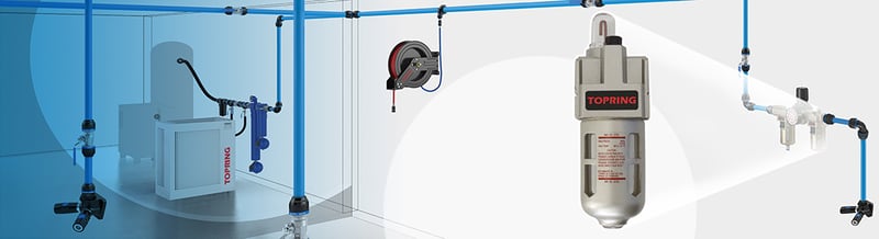
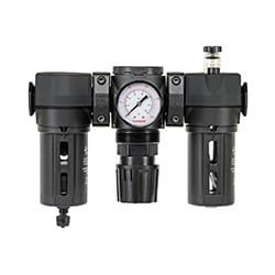
Lubrication of pneumatic tools and equipment
As important as it is, lubrication of pneumatic equipment and tools is often a forgotten part of air treatment.
When you take a close look at pneumatic tools, you quickly realize that these are often machines that are extremely stretched in terms of capacity. For example, it is not uncommon to find 1/2" impact wrenches that have a rotation speed of more than 8000 RPM! We can also cite the example of small grinders that work at 16,000 RPM! This high level of stress on the mechanisms subjects the tool to such high levels of stress that the slightest friction or heat can have a catastrophic effect on its lifespan. A pneumatic tool is a motor. And a motor, whatever it is, requires adequate lubrication.
Although lubrication is most often associated with fast-running engines, other equipment also requires proper lubrication. For example, pneumatic cylinders work continuously and at very high speeds.
Lubrication not only ensures that the tool lasts over time, but also that it achieves its intended result. A well-lubricated impact wrench guarantees the torque it claims. An unlubricated or poorly lubricated sander turns much slower and cannot provide the required sanding quality. But what are the right conditions that allow the user to be sure of good lubrication of their pneumatic tools and equipment?
How lubrication of pneumatic tools and equipment works
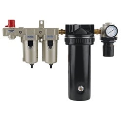
The lubricator is always positioned after filtration and then regulation. This is the last part of the air preparation at the point of application (FRL).
The air must be clean, as the principle of the lubricator does not tolerate impurities. This prevents impurities from clogging an internal duct and impairing proper operation. The filter ensures this first requirement. But the oil used, to be perfectly pulverized, also requires a stable and constant pressure, hence the need to regulate the air pressure.
Lubricators consist of a body (or head block) through which the air flow passes, and a bowl (or tank) underneath (to contain the oil reserve).
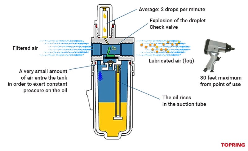
The principle of the lubricator (here we are talking about the oil mist lubricator which is by far the most common system) is in itself very simple:
- The air flows straight through the head block.
- As soon as it enters the lubricator, a small hole allows a small amount of air to enter the bowl, which pressurizes the oil volume.
- A very thin tube (the cannula) allows the lubricant to rise to a small cap located above the head block thanks to this pressure.
- In this cap, one can easily see a small cane-shaped tube from which the drops of oil flow slowly but regularly.
- From there, through a small passage, these drops fall progressively into the compressed air flow.
- The shock of the encounter between the compressed air (circulating at high speed and under pressure) and the drop of oil causes the latter to explode into a mist sprayed into the flow.
- This causes the oil particles to lubricate the air entering the machine or tool mechanism.
The amount of oil injected into the compressed air stream is adjustable by means of a screw usually located on the body of the lubricator. It acts as a small valve, allowing a greater or lesser flow of lubricant into the upstream nozzle.
A few basic rules
The operation of the lubricator is quite simple, as long as you follow a few important rules.
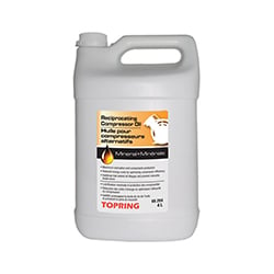
Oil quality
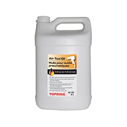
Do not confuse compressor oil with air tool oil. Air tool lubricant must have a very high fluidity. The particles in the oil will literally explode on contact with the air stream. The more fluid the oil, the more volatile the mist. An ISO VG32 rated oil is required. Make sure the label says "air tool oil". Any other type of oil will be too heavy and therefore not suitable.
Oil dosage
Pay attention to the oil flow setting. Too much oil is harmful and "drowns" the motor, in addition to generating costly overconsumption of the lubricant; not enough oil causes rapid deterioration of the tool. The proper dosage is one drop every 30 seconds. At this rate, lubrication is fair, efficient, and economical.
Proximity to the point of application
During a few visits to workshops, I have noticed installations where the lubricator is installed at the compressor outlet. The workshop manager thinks that the whole network benefits from the lubrication... Wrong! After a certain distance, the airborne oil particles fall back. The maximum distance between the lubricator and the tool should not exceed 10 meters. Beyond that distance, it doesn't work! When you are too far away, use a handheld device to get closer to the tool. You can install the lubricator on the rolling shop console used by the mechanic.
Please note: some applications do not allow oil!
This is the case, for example, for blowing, inflating, or painting stations. These applications must therefore each have their own hose connected by a connection with a different profile from the others, which will be lubricated. Equipping your workshops with two different end profiles is an ideal solution in this case and at zero cost... And we like that!