

Series 49 - Instructions manual - 49.400-49.452
Table of contents
1. General information
2. Basic safety instructions
3. Qualified operators
4. Safety
5. Storage
6. Transport and handling
7. Compressed air installation diagram
8. Dryer operating principle
9. Installation
10. Operation
11. Normal operation
12. Controller instructions
13. Safety systems
14. Preventive maintenance
15. Anomalies
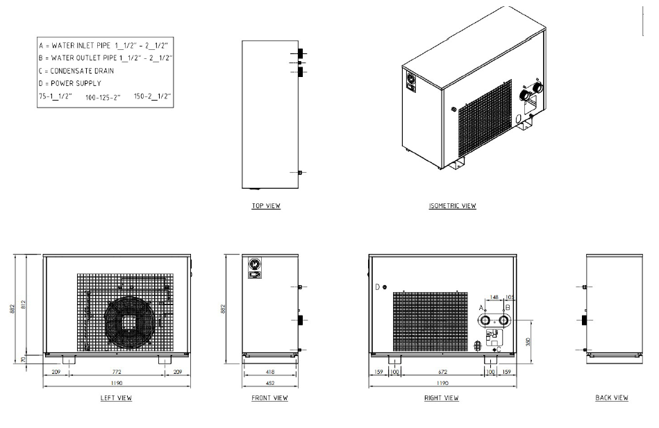
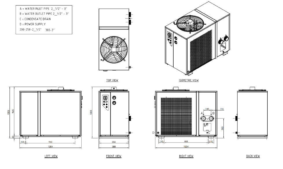
16. Dimensional plans
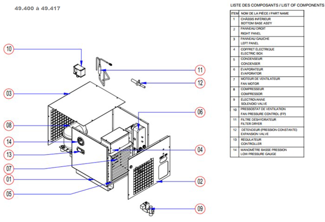
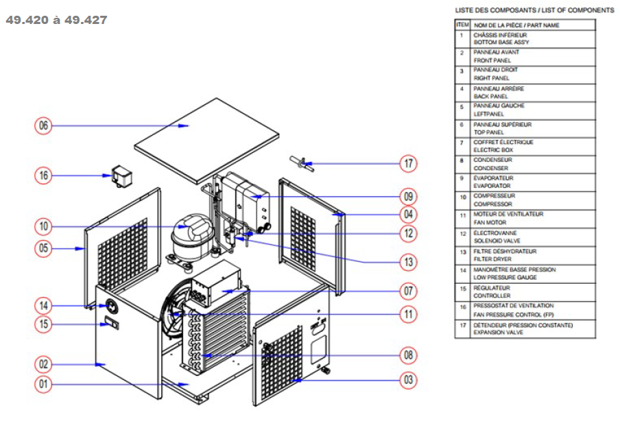
17. Exploded vues
18. Electrical diagrams
19. Range overview
20. Refrigerant gas safety data sheet
General
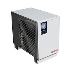
This manual is intended for anyone who uses or works on the refrigeration air dryer, particularly operators.
The refrigeration air dryer and this manual are protected by copyright. Any reproduction of these materials will be subject to
legal action.
All rights reserved by Toprings LTEE, in particular the rights of reproduction and distribution, as well as translation, including
those relating to complaints of copyright infringement. It is strictly prohibited to reproduce, process, duplicate, or distribute this
document in whole or in part using electronic or mechanical means without the prior written permission of Toprings LTEE.
This document may contain errors and is subject to change without notice.
Detailed Machine Identification Code
PRODUCT CODE : 49.400 to 49.452 |
|||
| TDX | XXXX | - AA - | XXXX Z |
| Name of the range | model number | Version and evolution | Increment and year of manufacture |
Warranty
The unit described in this manual is subject to the following warranty, which is considered to be automatically accepted and signed by the customer on the date of placing the order with Toprings LTEE. The supplier guarantees the proper performance and quality of the equipment supplied and undertakes, during the warranty period specified below, to repair or replace, at its discretion and as soon as possible, any parts that, upon examination, prove to be defective due to a materialdefect, construction or manufacturing defect, rendering them unsuitable for the use for which they are designed. This is subject to the absence of negligence on the part of the buyer, deterioration caused by normal wear and tear, negligence or misuse on the part of the user, damage caused by third parties, force majeure, or in all cases of damage resulting from other causes not attributable to defects in the quality of the workmanship.
The supplier shall in no event be liable for direct or indirect damages of any kind or for any reason whatsoever. The warranty shall be automatically void if the units covered by the claim have been repaired or modified in any way. The warranty and its conditions specified above are subject to the buyer's obligation to pay for the equipment and comply with the contractual commitments. No employee, sales representative, or After-Sales Service Center of Toprings LTEE, nor any other person, is authorized to grant any exemption from the warranty and the above conditions.
For further information, please refer to the general terms and conditions of the contract signed on the date of purchase, which are the only valid terms and conditions.
General Recommendations
 Before starting the units, carefully read the contents of this manual.
This service and maintenance manual describes the design, operation, and instructions for use and maintenance of the units marketed by Toprings LTEE.
Toprings LTEE is not liable for any damage resulting from failure to follow the instructions in this manual.
If you have any questions or require further clarification, Toprings LTEE's qualified technicians are available to provide all the necessary information.
To facilitate the identification of units, it is important to always specify the technical characteristics printed on the label affixed to the outside of the units, in particular the serial number.
The unit must not be operated under conditions other than the theoretical conditions, even for a short period of time.
Any part that does not guarantee safety must not be installed.
Basic Safety Instructions
The unit must be equipped with an emergency stop button by the installer. The installer must check that this has been done before starting the unit.
The unit is equipped with protective covers for its components. If the unit is installed outdoors, a canopy must be provided to protect it from snow, which could pose a risk during operation if the fan blades freeze.
Replace all damaged or missing supply lines for the various energy sources.
The refrigerant used for the entire range is R513A. It is not harmful if not inhaled. It only poses a hazard if it saturates the environment. Some fluids are flammable under certain conditions. See the specifications for each fluid in the safety data sheet at the end of the manual.
Protective gloves must be worn when handling the compressor lubricant. The lubricant must not be swallowed.
For all work related to installation, commissioning, equipment, use, changes in operating conditions and methods, routine maintenance, inspection, and periodic maintenance, follow the procedures outlined in the relevant chapters of this manual. Keep the manual handy for quick reference.
The unit must be used under the conditions specified in this service and maintenance manual.
Certain recommendations are given below for the USER, who must avoid abnormal operating conditions. Any operating conditions other than those expressly described in this manual must be avoided.
Do not climb on the unit.
Operate the unit once it has been correctly installed in the recommended position;
Do not start the unit without the protective covers properly installed.
Do not remove the guards while the unit is operating.
Do not remove the guards when the unit is powered on;
Do not clean the unit while it is in operation.
Do not install the unit in corrosive or explosive locations.
Do not disconnect or remove any parts or safety devices.
It is prohibited to use the unit in conditions other than those specified in this manual.
Toprings LTEE declines all responsibility for any damage caused either directly or indirectly by persons or elements as a result of failure to comply with these instructions.
Any assembly/disassembly carried out by the USER that is not provided for in this manual or authorized by Toprings LTEE will be considered improper use, thereby compromising safety functions and voiding the warranty.
Qualified Operators
Only the professionals specified below are authorized to operate the unit after receiving all the necessary instructions contained in this manual:
Specialized maintenance electrician
The electrician must have a general knowledge of electrical equipment as well as specific experience with control cabinets and electrical components of cooling units or similar equipment in the air conditioning sector. The electrician is only authorized to perform the specific operations indicated in this manual, strictly following the instructions provided.
Maintenance technician
Maintenance technicians must have general mechanical experience and specific experience with chillers or similar equipment in the air conditioning sector. Maintenance technicians are only authorized to perform the specific operations indicated in this manual, strictly following the instructions provided.
Refrigeration technician
Refrigeration technicians must have a specialized diploma obtained from a technical institution for similar equipment or operations under the authority of competent personnel. Refrigeration technicians are only authorized to perform the specific operations indicated in this manual, strictly following the instructions provided.
Transport operator
Transport operators may only perform the specific operations indicated in this manual, strictly following the instructions provided.
Personnel assigned to start-up and shutdown of the unit
(Basic operator and mechanic operator) After reading the information contained in this manual, the basic operator will be authorized to operate the unit manually for the following functions: start-up, shutdown, alarm display. In this case, the operator may only perform the specific operations indicated in this manual, carefully following the instructions provided.
Safety Manager
The Safety Manager is responsible for protection and risk prevention in the workplace, in accordance with European Directive 89/391/EEC (Safety in the Workplace) or any other national/local directive. The Safety Manager must ensure that all persons operating the unit have received all the necessary instructions contained in this manual, in particular those relating to initial installation and commissioning.
Safety
Essential safety rules
Warning
Before operating or maintaining this machine, read this paragraph carefully and understand its contents. The machine is connected to hazardous power circuits (electricity, pneumatic circuit, etc.) and must be used with the utmost caution. This paragraph explains what must be understood in terms of safety before operating or maintaining the dryer. Failure to follow these safety instructions may result in injury or death, or damage to the machine, products (inserts), or facilities, or even a serious accident.
Operator
- Before using or maintaining the dryer, you must complete a training course on the operation and maintenance of the device.
- Use and maintain the dryer with the approval of the system manager.
- It is very dangerous to allow a person with little knowledge of the system and insufficient understanding of how the machine works to use and maintain it incorrectly and carelessly.
Before operating the dryer
- Anyone who uses or maintains the dryer must carefully read this manual and understand its contents. Pay particular attention to the explanations labeled "Danger," "Warning," and "Caution" and fully understand them. Follow the instructions and avoid any foreseeable dangers when using or maintaining the dryer.
- Before operating or performing maintenance, read and understand the safety instructions in this manual and the safety labels on the device, and follow the instructions. Failure to do so may result in injury to your face or death, or the dryer, products (wafers), or installation may fail or cause serious damage.
- Other safety instructions are provided in other sections.
Warning labels (Warning)
- Warning labels are very important. Do not remove them intentionally.
- If they become soiled and illegible, accidentally removed, or lost, replace them with new labels in their original location.
Danger Warning
When using or performing maintenance on the dryer, observe the following three levels of warning. Understand their content and act accordingly. Warning messages are shown on warning labels affixed to the dryer and in the Safety Instructions section of this manual.
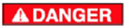
"Danger" messages warn of actual hazards and indicate the risk of death or serious injury to the operator if safety instructions or guidelines are not strictly followed to avoid such hazards. They also warn of the risk of accidental gas leaks or fire in the event of improper handling. The content of the messages is identical to warning messages but indicates a higher level of severity. Danger labels are generally displayed on a red background.
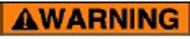
Warning messages alert users to actual hazards and indicate the risk of serious injury or death to operators who do not strictly follow safety guidelines or instructions to avoid such hazards. They also warn of the risk of accidental gas leaks or fire in the event of improper handling. Warning labels are generally orange in color.

Caution messages warn of actual dangers and indicate the risk of minor injury to the operator or damage to the system, products (plates), and equipment if the operator does not strictly follow the safety instructions or guidelines to avoid such dangers. Warning labels are generally displayed on a yellow background.
Storage
Store in a sheltered place:
- direct sunlight, rain, wind, and sand.
- Temperature: minimum 0°C / Maximum +50°C
- Maximum relative humidity: 90%
Transport and Handling
The carrier is always liable for any damage caused to the products entrusted to them during transport. Before preparing the unit for installation and commissioning, a complete visual inspection must therefore be carried out to check that the packaging crates are intact and that the unit shows no apparent damage or leakage of oil or refrigerant. Also check that the units correspond to those ordered.
Any damage or complaints must be reported to Toprings LTEE as soon as possible at 1-800-375-1828 or info@topring.ca.
In the event of damage to one or more components, do not start up the unit and inform Toprings LTEE of the problem at 1-800-375-1828 or info@topring.ca, agreeing with them on the action to be taken.
It is preferable to remove the packaging at the actual installation site.
Handling in premises must be carried out with the utmost care, without using the unit's components as handles. To avoid damage, it is essential that the units remain in the position intended for their operation during handling.
Do not leave units in their packaging in areas exposed to strong sunlight, as ambient temperatures could affect the trigger values of the safety devices.
The water circuit (specific to water-cooled versions) must be completely drained before handling the unit.
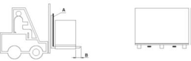
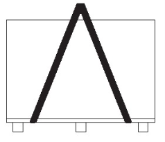
Lifting should preferably be carried out using a forklift truck. Use a spreader bar if using straps or slings, ensuring that no pressure is exerted on the outer edges of the units or the packaging crate.
During transport, DO NOT place the dryer on its side on the ground to avoid any potential problems.
Example of lifting with a forklift truck:
-
Insert protection for the outer structure of the unit, such as a sheet of cardboard or polystyrene (A).
- Ensure that the forks of the forklift extend at least 100 mm (B) beyond the unit.
Example of lifting using slings:
- Place the slings as shown.
- Place rigid structures on the upper sides of the unit to prevent damage (only if there is a point where pressure is applied).
- Tighten the slings gradually, ensuring they are correctly positioned.
- Begin lifting the unit.
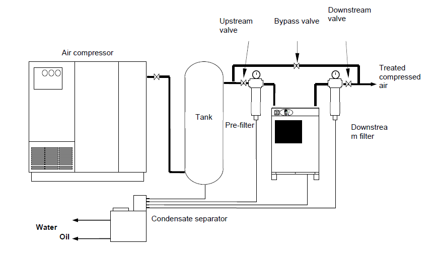
Compressed Air Installation Diagram
Be careful not to overtighten the screw connections on the evaporator inlets and outlets to avoid damaging the
heat exchanger of the dryers 49.400 to 49.452.
How the dryer works
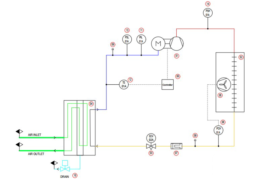
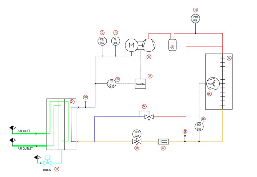
Schematic diagram
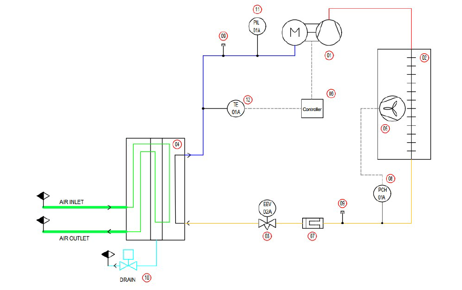
Model 49.400 to 49.442
Model 49.445 to 49.452 (and TDX0340-0725)
Model : TDX0950 - 1350
Operating Principle
-
Compressed air at high temperature and high humidity (100% relative humidity) from the compressor enters the dryer through a combined freon/air circuit plate heat exchanger. It is pre-cooled by the outgoing, treated, colder air. It then passes through the second section of the exchanger (air/freon) to be cooled.
- The air is cooled to a pressure dew point temperature of 3°C. This cooling is controlled by the refrigeration circuit. During this phase, the saturated vapor is converted into condensed water, which is then evacuated via the drain integrated into the plate heat exchanger (automatic drain).
- In the case of high flow rates, starting with the TDX0950, a hot gas valve regulates the temperature in the evaporator by adjusting the volume of refrigerant gas and controlling the constant dew point. This prevents excessive cooling and maintains the cooling temperature of the compressed air at a constant level.
Installation
Note: These instructions help ensure the longevity of the equipment. Please read them carefully and follow them.
Dryer Location
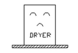
|
1) Place the dryer on a level surface. | |||
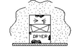
|
2) The dehumidifier can quickly become corroded if placed on a surface contaminated with acid or alkali. | |||
|
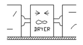
3) The installation site must be clear and have sufficient space. Blocked air circulation reduces the dehumidification rate and the life of the dryer. Allow 1,5 m of clearance around the dryer to ensure correct dryer operation | |||
|
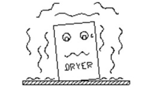
4) The installation site must be perfectly clean and vibration-free. ※ If this is not possible, clean the condenser regularly with compressed air. (Once a week or every two weeks) for models with a fan condenser. |
|||
|
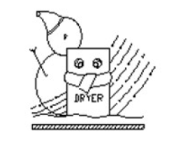
5) The ambient temperature of the installation site must be above (+5°C to prevent the dryer from freezing in winter, and the installation site must not be exposed to direct sunlight. (Ambient temperature: +5°C ~ +43°C). ※ If the installation site is confined, adequate ventilation must be provided to prevent malfunction. ※ If the ambient temperature in winter is below +5°C, contact our technical/after-sales service for information regarding use. |
|||
|
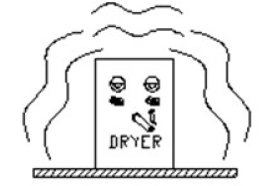
6) The installation site must be free of flammable products. | |||
Pipes
Pipes must be installed using standard tools and connected in such a way as to prevent any air leaks at the connections. Malfunctions and losses in the circuit can also be prevented by ensuring that the installation is properly adjusted to allow for possible movement and loosening of the connections for various reasons.
|
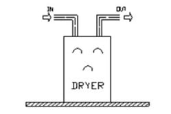
1) Pipes must be installed in accordance with the direction of compressed air flow after checking the inlet and outlet of the air dryer. (Installing the pipes in the wrong direction will cause the air dryer to malfunction). Similarly, in the case of a W model, the water connections to the condenser must comply with standard plumbing practices. A Y-strainer must be installed upstream of the condenser (inlet) to protect the plate heat exchanger from particles that could clog it. |
|||
|
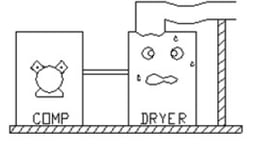
2) Pipes must not rest directly on the air dryer, but must be supported on a bracket to isolate them from the unit. | |||
|
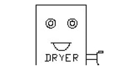
3) Condensed water coming from the drain outlet must be drained through a separate pipe. | |||
|
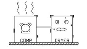
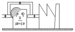
4) The air dryer must be isolated from the vibrations of the air compressor. A constant installation height must be maintained and vertical pipe installation must be avoided. | |||
|
5) The installation of a bypass pipe is recommended to facilitate repair of the air dryer. | |||
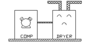
|
6) Galvanized/non-corrosive pipes are recommended for greater durability. | |||
Electrical Connections
- Connections: Use conductors that allow current to flow under maximum conditions (see specifications and recommendations on the technical data sheets). Use only cables that comply with UL and NEC (National Electric Code) and CEC (Canadian Electrical Code) standards.
- Use appropriate protection to prevent excessive current and short circuits. These must be installed before the dryer is put in place.
- Connections must be made in accordance with current standards.
- Possible current variation +/- 5%.
- Refer to the electrical diagrams included in this manual or contact Toprings LTEE support.
Operation
Operational Test
Start up the air dryer after performing the following checks:
Component check:
- Do you notice any problems with the air circuit or electrical circuit?
- Is the bypass valve closed?
- Is the purge circuit valve open?
- Is the compressed air pressure sufficient?
- Is there a difference between the permissible rated voltage and the breaking capacity of the fuses and circuit breaker?
- For models with a water condenser, supply the dryer with water.
Operating procedure
For all models, the dryer is started using the power buttons on the controller. Press the "ON" power button (press and hold the button on the front of the controller for CAREL controllers).
For all models in the TDX range, we recommend starting the dryer before opening the air inlet and outlet valves for five minutes. After starting the dryer and running it for five minutes, slowly pressurize the dryer to avoid any possible damage. The condensate drain must be active and functional. You can then open the outlet valve to the compressed air network.

Normal Operation
 Only start the dryer once you have thoroughly tested the compressed air circuit, the refrigeration circuit, and the electrical connections.
- Close the dryer isolation valves and open the bypass valve.
- Check the controller or switch to ensure that the dryer is in the off position.
- Start the air compressor.
- Start the dryer either using the switch or the controller.
- The refrigeration compressor and condenser fan will start after a 2-minute safety interval.
- Pressurize the dryer by slowly opening the air inlet valve.
- Slowly open the air outlet valve and then close the bypass.
- Check that the condensate drain opens during the defined interval or during tests performed on the Carel controller.
The dryer is now ready for normal operation.
Controller Instructions
User interface - CAREL controller
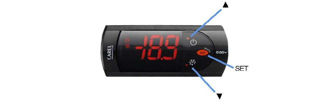
Changing parameters
- Press the SET button for more than 3 seconds until PS (Parameter setting) appears. The screen will then display the code for the parameter to be modified.
- Use the up and down arrows to scroll through the parameters. (see table below)
- Press SET to display the value associated with the parameter
- Increase or decrease the value using the arrows.
- Press SET to temporarily save the new value and return to the parameter name display.
- Repeat the above procedure for the other parameters.
- Press the SET button for more than 3 seconds to permanently save the settings and exit the modification procedure. (If this last operation is not performed, the display will return to its normal state after a certain amount of time and the temporarily saved changes will not be applied).
Parameter table
Parameters |
Description |
min |
max |
Default |
unit |
| /4 | Selection of the displayed probe (1*) | 1 | 3 | 1 | N/A |
| /C1 | Probe 1 offset (2*) | 10.4 | 53.6 | 28.4 | °F |
| /C2 | Probe 2 offset (not used) | 10.4 | 53.6 | 28.4 | °F |
| /C3 | Probe 3 offset (not used) | 10.4 | 53.6 | 28.4 | °F |
| Set | Set point | 30 | 176 | 30 | °F |
| Rd | Control differential (not used) | 32 | 176 | 32 | °F |
| P1 | Auto purge duration | 0 | 999 | 4 | Second |
| P2 | Time interval between two auto flushes | 0 | 999 | 2 | minute |
| P3 | Short cycle of manual purge | 0 | 999 | 1 | minute |
| P4 | Long cycle of manual purge | 0 | 999 | 0 | minute |
| AL (not used) | Threshold/Deviation for low temperature alarm | -58 | 302 | 32 | °F |
| AH (not used) | High temperature alarm threshold/difference | -58 | 302 | 32 | °F |
(1*) In the TDX dryer, only probe no. 1 is used. Be careful not to change this setting.
(2*) This offset allows for the effects of heat transfer between the probe and the measured medium. Do not change this setting.
Change in frequency and operation of purge
General
Condensate drainage is triggered automatically every 2 minutes (parameter P2 of the CAREL controller) for a duration of 4 seconds (parameter P1 if CAREL controller). The factory setting corresponds to the nominal operating conditions of the dryer. However, you may need to:
- Increase the purge duration and possibly the purge frequency if the temperature of the air to be treated is higher than the nominal value and if you find water in the liquid phase downstream of the dryer.
- Decrease the purge duration and possibly the purge frequency if the temperature of the air to be treated is below the nominal value (in the case of a final water cooler after the air compressor) or if the compressed air to be treated is not saturated with moisture (pre-drying or partial expansion).
The purpose of correctly adjusting the purge time is simply to limit the compressed air leak to the minimum required for this
operation. A correctly adjusted purge is characterized by:
- the expulsion of condensate (water/oil emulsion) during most of the purge.
- a brief jet of dry, condensate-free compressed air at the end of the purge
Manual purge operation
Short Cycle:
- Press the purge icon for 1 second
- The screen displays "Sho" for the first three seconds
- Release the button to start the short purge cycle (see parameter P3)
Long Cycle:
- Press the purge icon for several seconds
- The display shows "Sho" for the first three seconds, then "Lon"
- When "Lon" appears, release the button to start the long purge cycle (see parameter P4)
Purge Test
General
The purge test is required during:
- Initial commissioning
- Routine checks,
Procedure
- Press the down arrow for 1 second. Check that the solenoid valve opens and that condensate flows out. Check that the purge icon lights up on the Carel interface.
- The solenoid valve closes and condensate purging stops.
- Wait 5 minutes and check that the purge is working correctly again.
- If necessary, correct the purge time by referring to §5.4.
Note: When the solenoid valve is open, it will close automatically at the end of the programmed purge time.
Safety System
The dryer has a safety system that shuts down the appliance when triggered.
Electrical circuit
The motor protection system shuts down the dryer via the thermal relay when the air compressor is overloaded.
Restart
- Eliminate the problem that caused the device to shut down (see Troubleshooting).
- Press the start button to restart the dryer.
Routine Maintenance
Daily Maintenance
- Check that the automatic drain is properly draining water or compressed air.
- Check for air leaks at the pipe connections.
- Maintain the compressed air inlet temperature and ambient temperature at a constant level (38°C).
- Clean the dryer condenser and secondary cooler at regular intervals (once a week or every two weeks).
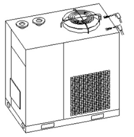
Regularly clean the condenser using a vacuum cleaner, brush, or compressed air gun. Poor heat exchange efficiency and the dryer shutting down due to the safety system being triggered in the event of a serious malfunction will affect the condenser's operation.
Management in the Event of Malfunction
-
R-513A Below 2 bars (29 psi): Refill the refrigerant gas if the volume is insufficient (check for leaks). Above 4 bars (58 psi): Remove a certain volume of refrigerant gas if the volume is excessive.
Preventive Maintenance
More and more compressed air networks contain significant impurities, so we recommend installing CF range compressed air filters in the appropriate grades upstream and downstream. If there are no CF filters upstream of the installation, we ask that you replace the screen filter of the automatic drain of the dryer after 200 hours of use.
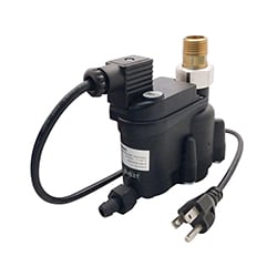
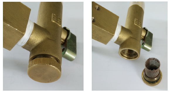
TDX direct expansion refrigeration dryers have a solenoid valve condensate drain system. This system consists of brass fittings and a solenoid valve block, connected directly to the separator outlet. The solenoid valve block is protected by a screen filter (accessible and removable) that captures any solid impurities that may be present in the compressed air passing through the dryer. If these impurities pass through the filter, the solenoid valve coil may become blocked, overheated, and cause the drain system to fail. This failure is dangerous for equipment downstream of the dryer, which would then be exposed to excessive humidity.
Replacement
To do this, the compressed air supply to the dryer must be shut off (e.g., bypass around the dryer) and the dryer must be depressurized (e.g., via the purge). Next, unscrew the access cap on the filter screen of the valve block.
Trouble Shooting
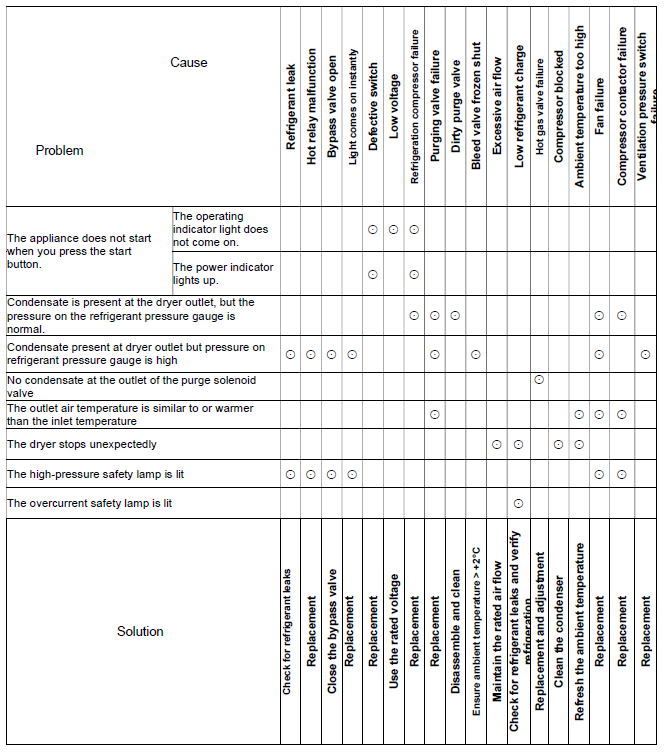
Refer to the table below if your dryer malfunctions.
Dimensional Plans
49.400 to 49.417
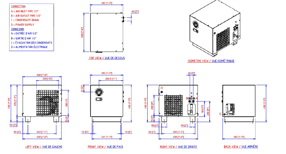
49.420 to 49.427
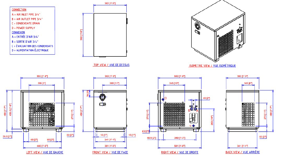
40.430 to 40.442
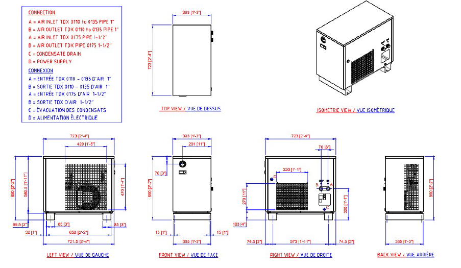
49.445 to 49.452
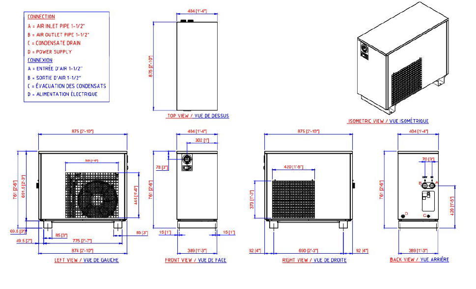
TDX0340 to TDX0725
TDX0950 to TDX1350
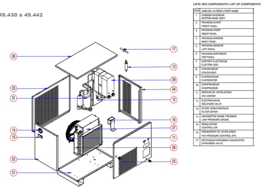
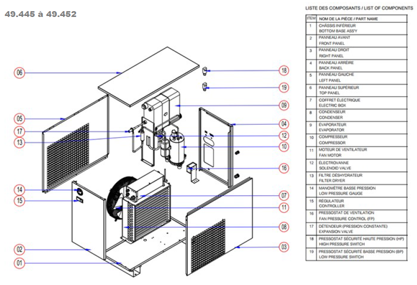
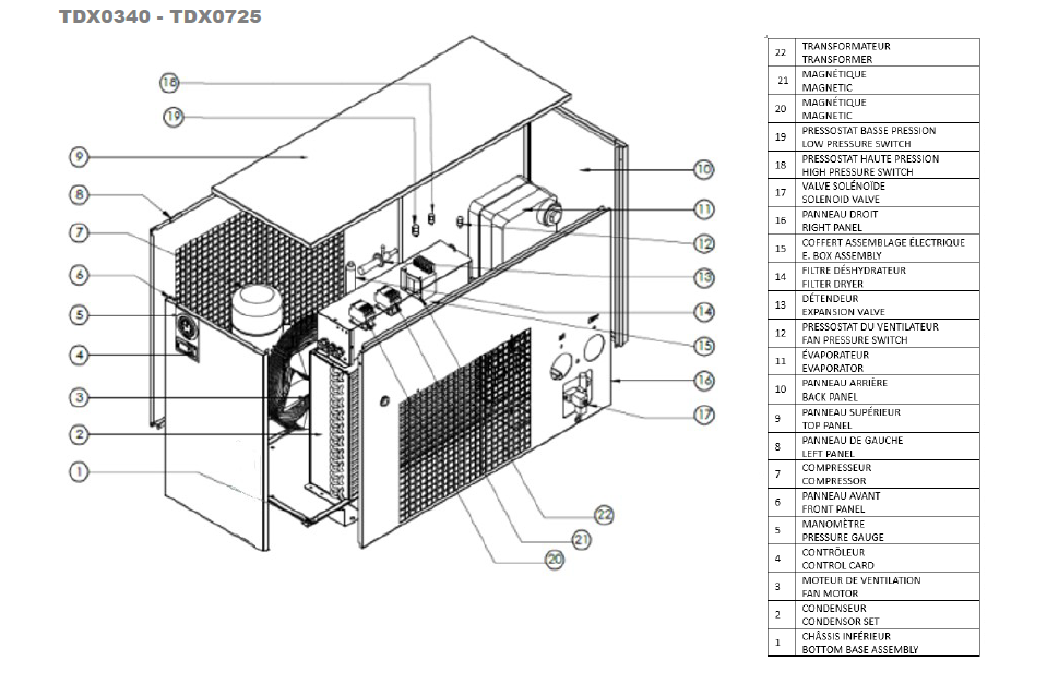
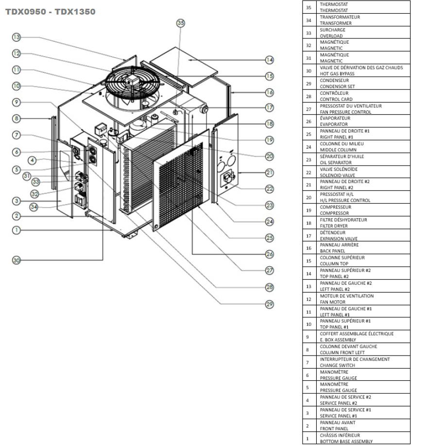
Exploded Views
Exploded views are presented by chassis type rather than by model. Some spare parts may be identical between two models. Some are different.
These views are provided to facilitate the identification of the parts concerned. Please always provide Toprings LTEE with the serial number and model of your dryer.
Toprings LTEE is committed to a policy of continuous optimization of its products, so these items may change without prior notice.
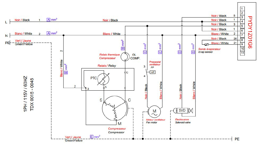
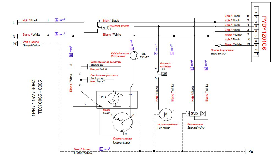
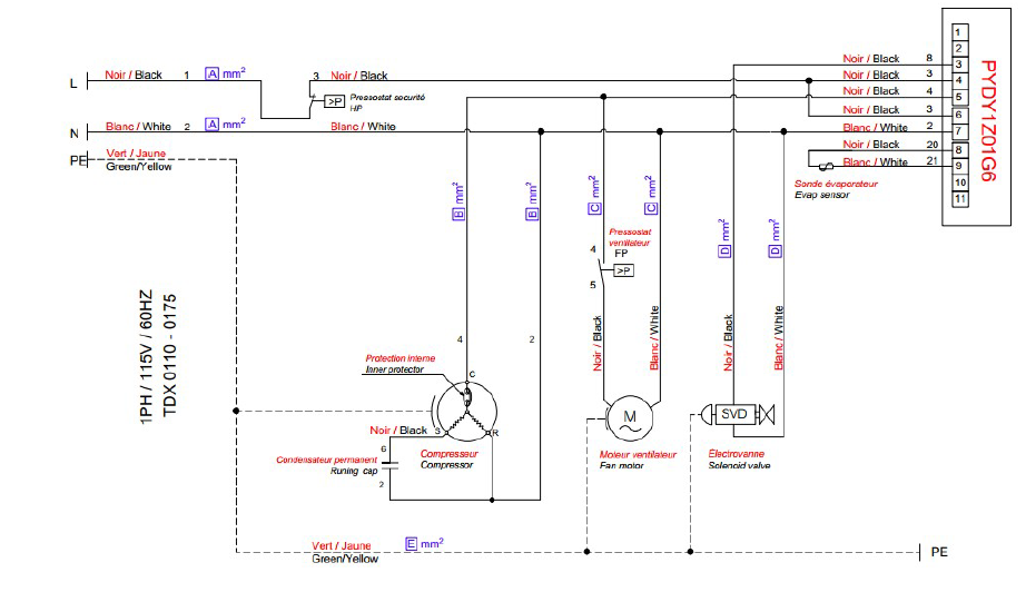
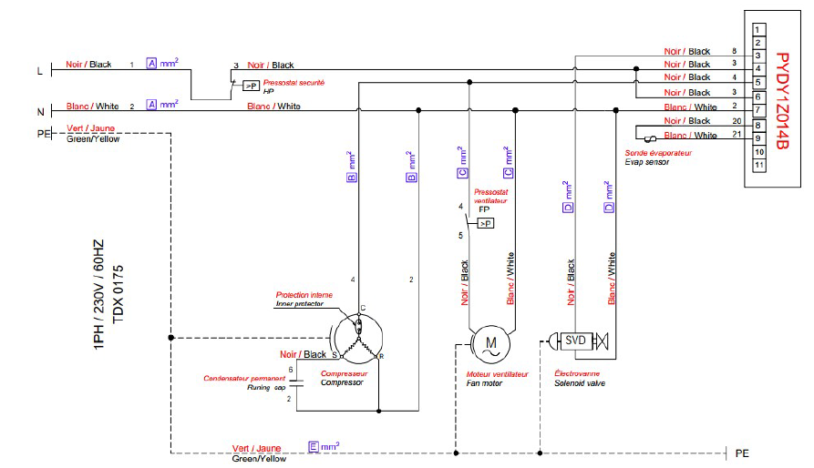
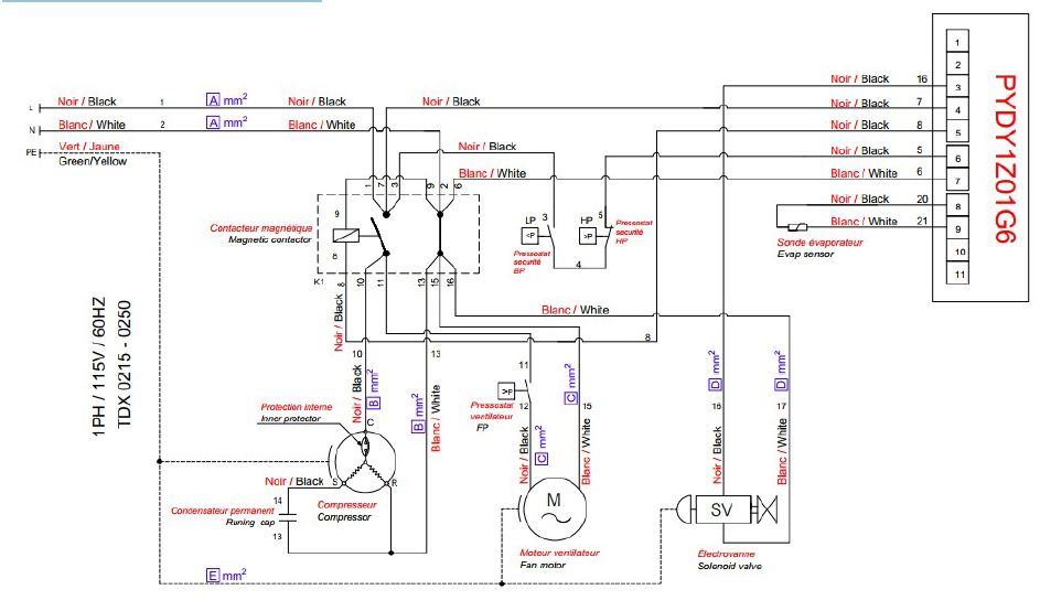
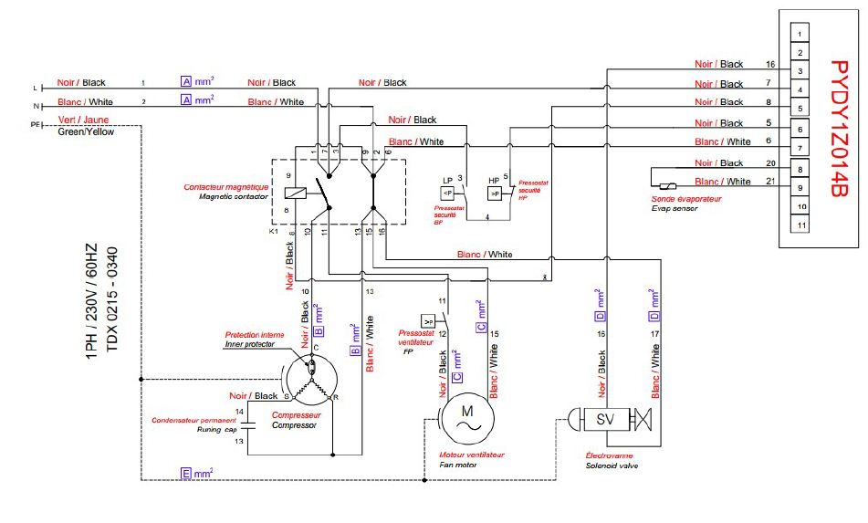
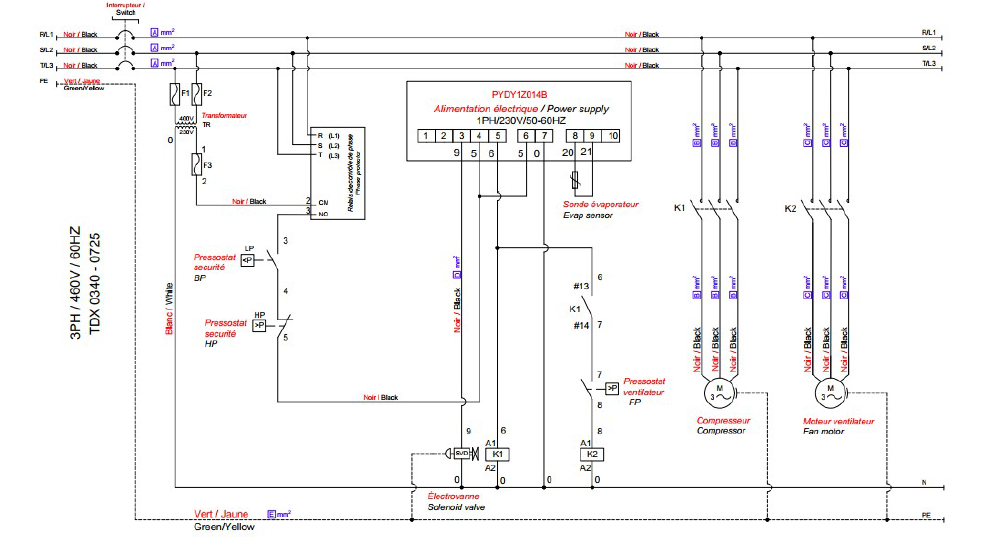
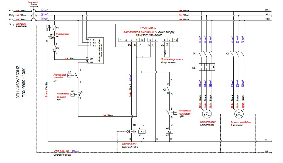
Electrical Diagrams
49.400 to 49.417 – 115V/1/60Hz
49.420 to 49.427 – 115V/1/60Hz
49.430 to 49.442 – 115V/1/60Hz
TDX0175 – 230V/1/60Hz
TDX0215 to 0250 – 115V/1/60Hz
49.445 to 49.452 and TDX0340 – 230V/1/60Hz
TDX0340 to 0725 – 460V/3/60Hz
TDX0950 to 1350 – 460V/3/60Hz
Range Overview
product code |
Product ref. |
Air flow |
Air inlet/ outlet |
Max Air Pressure |
Electric Power Supply | Nom P.Abs. |
Nom. Amp. |
Nb Circuits/ Fluid |
Length |
width |
Height |
Weight |
|||||||
| cfm | m3/h | inch | bar | psi | V/P/Hz | KW | A | U | mm | inch | mm | inch | mm | inch | kg | lb | |||
| 49.400 - 49.402 | TDX 0015 115V | 12 | 20 | 1/2" | 16 | 232 | 115-1-60 | 0.36 | 3.20 | 1/R513A | 450 | 17.72 | 382 | 15.04 | 430 | 16.93 | 25 | 55 | |
| 49.405 - 49.407 | TDX 0020 115V | 18 | 30 | 1/2" | 16 | 232 | 115-1-60 | 0.36 | 3.20 | 1/R513A | 450 | 17.72 | 382 | 15.04 | 430 | 16.93 | 28 | 62 | |
| 49.410 - 49.412 | TDX 0030 115V | 25 | 42 | 1/2" | 16 | 232 | 115-1-60 | 0.37 | 3.80 | 1/R513A | 450 | 17.72 | 382 | 15.04 | 430 | 16.93 | 26 | 58 | |
| 49.415 - 49.417 | TDX 0045 115V | 39 | 66 | 1/2" | 16 | 232 | 115-1-60 | 0.38 | 4.00 | 1/R513A | 450 | 17.72 | 382 | 15.04 | 430 | 16.93 | 27 | 59 | |
| 49.420 - 49.422 | TDX 0055 115V | 50 | 85 | 3/4" | 16 | 232 | 115-1-60 | 0.61 | 4.10 | 1/R513A | 502 | 19.76 | 382 | 15.04 | 480 | 18.90 | 38 | 84 | |
| 49.425 - 49.427 | TDX 0085 115V | 75 | 127 | 3/4" | 16 | 232 | 115-1-60 | 0.61 | 6.46 | 1/R513A | 502 | 19.72 | 382 | 15.04 |
480 | 18.90 | 42 | 93 | |
| 49.430 - 49.432 | TDX 0110 115V | 119 | 202 | 1" | 16 | 232 | 115-1-60 | 1.02 | 8.59 | 1/R513A | 723 | 28.46 | 393 | 15.47 |
650 | 25.59 | 65 | 143 | |
| 49.435 - 49.437 | TDX 0135 115V | 119 | 202 | 1" | 16 | 232 | 115-1-60 | 1.02 | 8.59 | 1/R513A | 723 | 28.46 | 393 | 15.47 |
650 | 25.59 | 65 | 143 | |
| 49.440 - 49.442 | TDX 0175 115V | 152 | 258 | 1-1/2" | 16 | 232 | 115-1-60 | 1.02 | 8.59 | 1/R513A | 723 | 28.46 | 393 | 15.47 |
650 | 25.59 | 69 | 152 | |
| On demand | TDX 0175 230V | 152 | 258 | 1-1/2" | 16 | 232 | 230-1-60 | 0.99 | 4.49 | 1/R513A | 723 | 28.46 | 393 | 15.47 |
650 | 25.59 | 69 | 152 | |
| On demand | TDX 0215 115V | 188 | 319 | 1-1/2" | 16 | 232 | 115-1-60 | 1.11 | 8.35 | 1/R513A | 875 | 34.45 | 404 | 15.91 |
761 | 29.96 | 89 | 196 | |
| 49.445 - 49.447 | TDX 0215 230V | 188 | 319 | 1-1/2" | 16 | 232 | 230-1-60 | 1.09 | 4.81 | 1/R513A | 875 | 34.45 | 404 | 15.91 |
761 | 29.96 | 89 | 196 | |
| On demand | TDX 0250 115V | 224 | 380 | 1-1/2" | 16 | 232 | 115-1-60 | 1.11 |
8.35 |
1/R513A | 875 | 34.45 | 404 | 15.91 |
761 | 29.96 | 101 | 222 | |
| 49.450 - 49.452 | TDX 0250 230V | 224 | 380 | 1-1/2" | 16 | 232 | 230-1-60 | 1.69 | 7.47 | 1/R513A | 875 | 34.45 | 404 | 15.91 |
761 | 29.96 | 101 | 222 | |
| On demand | TDX 0340 230V | 304 | 516 | 2" | 16 | 232 | 230-1-60 | 1.69 | 7.47 | 1/R513A | 1188 | 46.77 | 452 | 17.80 |
882 | 34.72 | 115 | 254 | |
| On demand | TDX 0340 460V | 304 | 516 | 2" | 16 | 232 | 460-3-60 | 2 | 3.58 | 1/R513A | 1188 | 46.77 | 452 | 17.80 |
882 | 34.72 | 115 | 254 | |
| On demand | TDX 0470 460V | 415 | 705 | 2" | 16 | 232 | 460-3-60 | 2 | 3.58 | 1/R513A | 1188 | 46.77 | 452 | 17.80 |
882 | 34.72 | 135 | 297 | |
| On demand | TDX 0550 460V | 498 | 846 | 2-1/2" | 16 | 232 | 460-3-60 | 2 | 3.58 | 1/R513A | 1188 | 46.77 | 452 | 17.80 |
882 | 34.72 | 145 | 319 | |
| On demand | TDX 0725 460V | 636 | 1080 | 2-1/2" | 10 | 188 | 460-3-60 | 2.87 | 4.87 | 1/R513A | 1188 | 46.77 | 452 | 17.80 |
882 | 34.72 | 180 | 396 | |
| On demand | TDX 0950 460V | 830 | 1410 | 2-1/2" | 10 | 188 | 460-3-60 | 2.87 | 4.87 | 1/R513A | 1221 | 48.07 | 586 | 23.07 |
1023 | 40.28 | 322 | 711 | |
| On demand | TDX 1150 460V | 996 | 1692 | 3" | 10 | 188 | 460-3-60 | 3.93 | 6.61 | 1/R513A | 1221 | 48.07 | 586 | 23.07 |
1023 | 40.28 | 349 | 770 | |
| On demand | TDX 1350 460V | 1189 | 2020 | 3" | 10 | 188 | 460-3-60 | 5.02 | 8.64 | 1/R513A | 1221 | 48.07 | 586 | 23.07 |
1023 | 40.28 | 403 | 888 | |
R513A Refrigerant Gas - Product Safety Data Sheet
Product name : R513A refrigerant gas
Substances / information on ingredients
| Name |
CAS-No. CE-No. Index-No. Registration Number |
Classification | Concentration (% w/w) | ||||
| 2,3,3,3-Tetrafluoropropene* |
754-12-1 468-710-7 01-0000019665-61 |
Flam. Gas 1B; H221 Press. Gas Liquefied gas; H280 | 56 | ||||
| 1,1,1,2-Tetrafluoroethane* |
811-97-2 212-377-0 01-2119459374-33 |
Press. Gas Liquefied gas; H280 | 44 |
Hazard Identification
Low acute toxicity. High exposure may abnormally accelerate the heart rate and cause sudden death. Very high concentrations in the air may have anesthetic effects and cause asphyxiation. Splashes or sprays of liquids may cause frostbite and burns to the skin and eyes.
First Aid
Emergency first aid for skin or eye contact and ingestion should be administered following exposure to the liquid or liquid splashes.
See also Toxicological Information.
|
Inhalation |
|
|---|---|
|
Skin contact
|
Thaw affected areas with water. Remove contaminated clothing. Caution! Clothing may stick to the skin in case of frostbite. After skin contact, immediately wash affected areas thoroughly with lukewarm water. In case of irritation or blistering, contact a doctor. |
|
Eye Contact |
Immediately flush with eye wash solution or clean water, keeping the eyelids open, for at least 10 minutes. |
|
Ingestion
|
Unlikely route of exposure. |
|
Treatment
Additional |
Treatment of symptoms and supportive therapy as indicated. The use of adrenaline-based drugs and similar sympathomimetic products should be avoided following exposure, as this could cause cardiac arrhythmia, resulting in a risk of cardiac arrest. |
Fire-fighting Measures
This refrigerant gas is non-flammable in air under ambient temperature and pressure conditions. Certain pressurized mixtures of this refrigerant with air may be flammable. Pressurized refrigerant + air mixtures should be avoided.
Certain mixtures of HFCs and chlorine may be flammable or may react under certain conditions. Decomposition under the effect of heat generates highly toxic and corrosive vapors (hydrogen fluoride). Tanks may burst if overheated.
Extinguishing media: Suitable for surrounding fire. Tanks must be sprayed with water to cool them down.
Fire protection equipment: Self-contained breathing apparatus providing full protection in case of fire must be worn. See also
Exposure Controls/Personal Protection.
Measures in Case of Accidental Leaks
Wear appropriate personal protective equipment (including respiratory masks) during the removal of accidentally spilled liquids. See also Exposure Controls/Personal Protection. If it is safe to do so, isolate the source of the leak. Allow small spills to evaporate with adequate ventilation.
Large spills: Ventilate the area. Contain spills with sand, earth, or any suitable absorbent material. Prevent liquid from entering drains, sewers, basements, or pits, as vapors may create a suffocating atmosphere.
Handling and storage
Handling
-
Avoid inhaling highly concentrated vapors. Concentration levels in the atmosphere must remain within the workplace exposure limit. Concentrations in the atmosphere can be kept well below the workplace exposure limit by good hygiene measures.
-
As the vapor is heavier than air, high concentrations may occur at low levels in poorly ventilated areas. In such cases, provide adequate ventilation or wear a suitable respirator with a good air supply.
-
Avoid contact with open flames and high-temperature surfaces, as corrosive and highly toxic decomposition products may form.
-
Avoid contact of the liquid with skin and eyes.
-
For proper refrigerant composition, circuits must be filled in the liquid phase and not in the vapor phase.
Storage
- Store in a well-ventilated area. Keep in a cool place away from fire hazards, direct sunlight, and all sources of heat such as electric or steam radiators.
- Avoid storing near the air intakes of air conditioners, boilers, and drainage pit openings.
- Tanks and drums: Keep away from moisture.
- Storage temperature: < 45°C
Exposure Controls / Personal Protection
-
Wear appropriate protective clothing, gloves, and safety glasses/face shield. Wear heat-insulated gloves when handling liquefied gases.
- In case of insufficient ventilation, in areas potentially exposed to high concentrations, wear an appropriate respirator with fresh air supply.
| Component | Cas n° |
Exposure value type | Control parameter | Source |
|
2,3,3,3-Tetrafluoropropene (R1234yf) |
754-12-1 | TWA | - | No limit value of exposure to workstations |
| - | ||||
| OEL | - | |||
| - | ||||
1,1,1,2-Tetrafluoroethane |
811-97-2 | TWA | 1'000 ppm | SUVA: Limit values of exposure to workstations |
| 4'200 mg/m³ | ||||
| OEL | - | SUVA: Limit values of exposure to workstations | ||
| - |
Stability and Reactivity
-
Hazardous reactions: Certain mixtures of HFC+HFO and chlorine may be flammable or reactive under certain conditions.
- Finely divided metals, magnesium, and alloys containing more than 2% magnesium. May react violently if in contact with alkali metals and alkaline earth metals – sodium, potassium, barium.
- Hazardous decomposition products: Hydrogen fluoride from thermal decomposition and hydrolysis.
Toxicological Data
Inhalation
High exposure can abnormally accelerate the heart rate and lead to sudden death. Very high concentrations in the air can have
anesthetic effects and lead to asphyxiation.
Skin contact
Splashes or sprays of liquid may cause frostbite. Harmful effects are unlikely if absorbed through the skin.
Eye contact
Splashes or sprays of liquid may cause frostbite.
Ingestion
Very low risk, but frostbite may occur if swallowed.
Long-term exposure
R513A: A lifetime inhalation study in rats showed that exposure to 50,000 ppm caused benign tumors of the reproductive organs. The tumor-promoting effects were only observed after prolonged exposure to high concentrations and are not considered significant for individuals exposed to R513A at or below the occupational exposure limit.
Ecological Data
Environmental conditions and distribution
High-tonnage product manufactured in fully contained facilities. High-tonnage product used in open facilities. Vapors.
Persistance and degradation
Relatively rapid decomposition in the lower layers of the atmosphere (troposphere). Atmospheric lifetime: 13.6 years. Halogenated hydrocarbon global warming potential (HGWP): 0.30 (relative to a value of 1 for CFC 11) or global warming potential (GWP) of 1300 (relative to a value of 1 for carbon dioxide over 100 years).
Effect on effluent treatment
Emissions from the product enter the atmosphere and do not cause long-term pollution of the aquatic environment.
Disposal
The best solution is to recover and recycle the product. If this is not possible, it must be destroyed in an approved facility equipped
to absorb and neutralize acid gases and other toxic industrial products.
We assume no liability for any technical specifications contained in this manual, which are subject to change without notice.