Each compressed air system project is unique, as the need for compressed air varies with the application and there are many configuration options. Optimal design at the outset of the project will ensure:
- Safety of the people who will be using the compressed air
- Lower operating costs due to system efficiency
- Ideal performance of pneumatic equipment and tools
So where do you start your project? How can you be sure that you are not overlooking anything and that the network you are implementing is truly adapted to the needs and requirements of your industry? Here is a list of the main elements to consider. Don't hesitate to ask an expert to help you.
If you'd rather watch a video than read the article, take a look at our training on network design.
The type of application
Each application requires different specifications (air volume, air quality). Before starting a project, ask yourself what will you be using your compressed air system for, for example:
- What air equipment or tools will be used?
- How often will it be used?
- What are the conditions of the working environment?
Compressed air requirements
Calculate the total airflow required to supply all of the pneumatic equipment and tools you plan to use. If necessary, refer to the air consumption table for the type of tool being used. The diameter of the air system should be large enough to deliver the required amount of air at the required pressure to all the sampling points.
- What are the compressed air requirements?
- How much air equipment and tools will be used?
- What volume of air (SCFM) do the pneumatic equipment and tools that will be used need to operate?
- How often will it be used (daily or occasionally)?
- How long will it be used (continuously or in fixed periods)?>
The layout of your facility
Make sure you know the layout of your plant or shop. This will have a major influence on the type of configuration you choose. Consider the location of the compressor, the distance to be travelled and any drops (descents) required. Take the time to sketch it out. The total length of the system in linear feet will influence the required pipe size and the preferred system configuration.
Reminder: Important questions for the enumeration and visualization of the configuration
- How is the plant layout configured?
- What are the workstation locations and layouts (tools and equipment)?
- Where will the compressor be located?
- How far does the air system need to go (total distance/size of the shop)?
- How many drops will there be?
Examples of workstation layouts

Guide for determining the tube diameter (mm) required for an air system
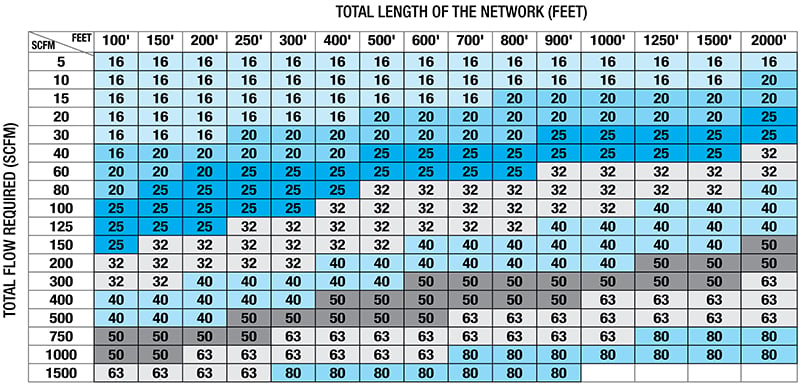 Data based on a closed loop network. Total air flow is the sum of all air flows required for each tool and pneumatic equipment.
Compressed air system configuration
The optimal configuration of a compressed air network is determined according to the layout of the plant or workshop. The goal is to achieve a balance between the demand in air volume, i.e. the flow rate measured in SCFM, and the pressure required in PSI. It's also important to think about and plan for your future needs, such as expansion projects. This step will allow you to determine the right diameter of the main network not just for your current requirements but also for the future. To learn about all of the options available to you, see the article The 5 Main Configurations of a Compressed Air System.
The two most common configurations:
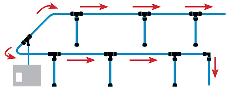
Closed-loop system
Closed-loop systems are considered the most efficient configuration. They promote uniform pressure between all compressed air sampling points. Prioritize this type of configuration if your layout allows it.
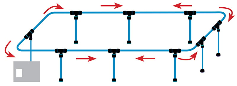
Linear system
Opt for a linear network when a closed-loop configuration is not possible. To feed the network in both directions, the compressor should ideally be located in the center of the network (from the compressor to the furthest point of use) or you could have more than one compressor.
Air quality requirements
The presence of water and contaminants causes equipment failure and promotes bacterial growth in the piping system. Some applications or processes require very high air quality standards. This is the case in the food, pharmaceutical, and nutraceutical industries.
- What air quality is required for each application or industry (some applications may require local air treatment such as an FRL unit or a desiccant dryer)?
- Do air requirements vary from tool to tool or equipment to equipment (provide filters, regulators, and lubricators at different application points)?
- What type of piping material should be used?
The ISO Standard
The International Organization for Standardization (ISO) has established the 8573 air quality standard to assist in the selection, design, and measurement of air handling components. Refer to this standard to see what requirements apply to your industry.
| Level 1 | Level 2 | Level 3 | Level 4 | Level 5 |
|---|---|---|---|---|
 |
 |
 |
 |
 |
| Compressed air without specification | General shop air: air tools (sand blasting, grinding) |
Air instrument
Spray painting
Powder coating
Packing machines
|
Food industry
Pharmaceutical and chemical industries
Laboratories
|
Food industry (breweries, dairies)
Pharmaceutical and chemical industries
Laboratories
|
| ISO 8573.1 Class 5.6.5 |
ISO 8573.1 Class 3.6.4 |
ISO 8573.1 Class 1.5.3 |
ISO 8573.1 Class 1.4.1 |
ISO 8573.1 Class 1.1.1 |
3 ways to treat the air in your system:
At the compressor outlet
Use a water separator to remove condensate at the air compressor outlet. Water separators use centrifugal force, a vortex effect, to remove up to 99% of water and solid contaminants from compressed air.
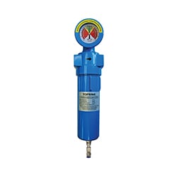
If your industry requires very high air quality standards, equip your system with filters at various strategic locations. The filters remove solid particles, water, and oil in aerosol and vapor form.
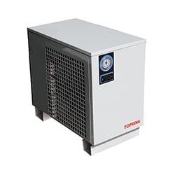
Lower the dew point of your compressed air with a refrigerant dryer. It cools the water vapors in the air and condenses them into liquid. The condensed water can then be drained and removed from any piping system.
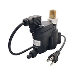
Use condensate drains to collect and remove water that accumulates in various parts of the system (e.g., air compressor receiver, water separator, filters, air dryer, and compressed air system downspouts).
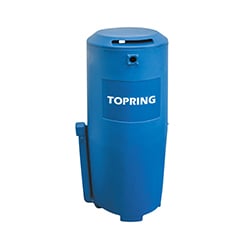
Dispose of water and condensate in the system in an economical and environmentally friendly way by means of a water-oil separator that intercepts the oil in the condensate.
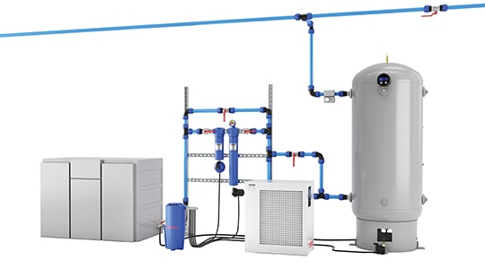
To learn more about air treatment options, see the article How to Remove and Treat Condensate at the Compressor Outlet.
At the Piping Level
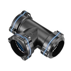
Even if you treat the air as it leaves the compressor, condensate can still accumulate in the piping, as water vapor will continue to cool as they enter the pipe. Provide take-off drop couplings and Te fittings with water trap insert when installing a drop on a new or existing system. These prevent water from the main line from entering the drops and limit condensate at the point of use.

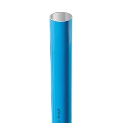
Choose materials that will not corrode or deteriorate. They allow air to flow freely without friction. See the section "Why is Aluminum the ideal choice" of Topring's 100% aluminum air system page to learn more about this solution.
At the point of use
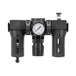
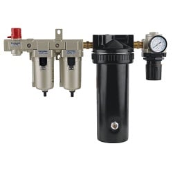
Processing compressed air at the point of use ensures safe air quality for tools, adequate pressure for the application, and lubrication of the tool or pneumatic equipment as required.
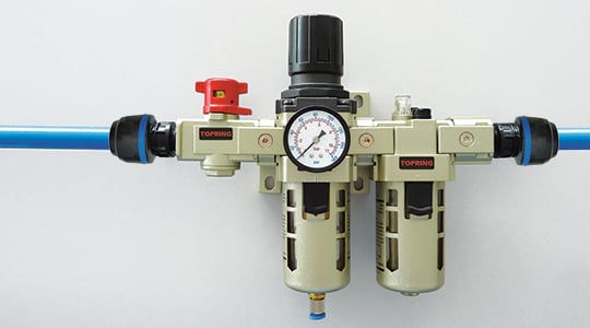
See the article Basics of Air Preparation (FRL) for more information.
Network installation
Although it may seem trivial, this last decision will determine much of the final value of your air system. Choose a qualified installer who knows the rules of installation and safety. Some systems are very simple to install, but it is essential that the installation be optimal. No matter what stage of design your air system is in, don't hesitate to call on one of our consultants to help you choose the components or simply for advice on installation.
Installing an aluminum network is 3 times faster than the conventional method of tapping the pipes. See for yourself in this video comparing aluminum and steel.
Some additional tips and tricks
Eliminate unnecessary compressor start-ups during downtime with a programmable shut-off valve installed at the air tank outlet. Program it to open and close automatically at the beginning and end of each shift. This type of valve allows a progressive opening of the valve and avoids any water hammer effect.
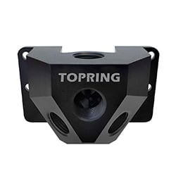
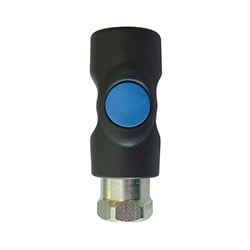
Each drop is connected to a point of use. Install a manifold (or distribution bar) with quick connectors to supply several tools and equipment simultaneously. Choose a manifold with a drain to ensure proper condensate drainage and eliminate condensate buildup at the ends of downspouts.
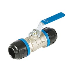
A compressed air system must be maintained regularly to ensure its efficiency. Plan for spare parts and maintenance tasks as soon as the system is installed so that you can perform your checks quickly and safely. Install a ball valve to isolate sections of the compressed air system. This will allow you to make repairs, connections, expansions, or periodic maintenance without having to shut down the entire compressed air system. Choose lockout ball valves and avoid the potential danger of accidentally turning the system back on when performing maintenance.
In conclusion
Remember that each compressed air piping system has its own unique features. Be sure to read the design and installation guide that comes with the system you have chosen to use for your air system project.
