
Series 08 Installation Guide
Table of Contents
Warnings and Responsibilities
Tools Required for Installation
Basic Rules
Pipe Preparation
Compression Fitting Installation
Compression Fitting Tightening
Adapter (Threaded) Installation
Compact Connection Fitting Tightening
Bypass Saddle Tee Installation (Depressurized System)
Bypass Saddle Tee Installation (Pressurized System)
Pilot-Operated Pneumatic Valve Installation
System Testing and Commissioning
Legal Notice and Limitation of Liability
Technical Specifications, Replacement Parts and Repair Kits
To consult the technical specifications, replacement parts list and repair kits available for your product, please visit the product page by searching for the product number (SKU) in the main menu's search bar.
Warnings and Responsibilities
Topring assumes no responsibility for the installation of any particular piping system. It is the responsibility of the project designer to ensure that the installer complies with the standards in force, in particular the installation guidelines for pipes (main line and drop legs) and components,
including the configuration of slopes and expansion loops.


Basic Rules
- Follow the system layout plan.
- Recommended minimum installation height: 2.5 m (8.2 ft) from the floor (for safety reasons)
- All horizontal piping must have a minimum slope of approximately 1% to allow proper condensate drainage. Downward slopes must lead to drain drops equipped with condensate drains, installed at the lowest points of the system.

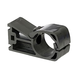
- Pipe support methods must be adapted to the building configuration and installed to ensure proper alignment and overall system rigidity.
- Maintain clearance from walls. To prevent expansion/contraction issues and ensure sufficient space, pipes must not be installed too close to walls.
- The maximum distance between supports must be 3 meters (10 ft), regardless of pipe diameter. It is strongly recommended to install a support 20–30 cm (8–12 in) on each side of a fitting, or 20 cm (8 in) on each side of a valve. This helps prevent pipe distortion.
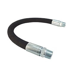
If installing a valve with an integrated support bracket, additional supports on each side of the valve are not required. - A flexible element (expansion loop, anti-vibration hose, or expansion fitting) must be installed on any straight section longer than 150 m (500 ft) to absorb expansion and prevent stress on the piping system. The distance of 150 m is valid for installations where the piping temperature varies no more than 20 degrees C relative to the building.
- Ensure all fittings are tightened to the recommended torque after pipe insertion.
- Pressurize the system gradually.
- Never work on a pressurized system.
Compressed Air System Installation
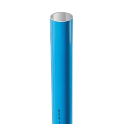
Pipe Preparation
Tools Required for Pipe Preparation:
|
|
|
|
|
|---|


1. Cut the pipe
|
|
|
|
|---|


2. Deburr and chamfer
Remove the shavings from inside the pipe to protect the sealing elements (O-rings) of the fitting.
Manual
|
|
With Drill
|
|


|
|
ATTENTION Wear safety glasses and protective gloves before performing this step. These steps are essential to facilitate installation and prevent damage to the fitting seal. |

3. Clean and lubricate the pipe
- Clean with a damp cloth.
- Use a mild, non-aggressive degreaser.
- To facilitate assembly, it is mandatory to lubricate the pipe.
- Use only Topring lubricant gel (08.579).
(The use of lubricants, oils, or grease with unverified chemical compatibility is strictly prohibited.)
Quick calculation for the required amount of gel:
|
Formula : (Pipe diameter in mm × number of fittings) ÷ 6400 Example : (Pipe 63 mm × 100 fittings) ÷ 6400 = ~1 bottle of gel |
|---|
Pipe Preparation Demonstration
|
If these instructions are printed, scan the QR code to access the video. |
|---|

Compression Fitting Installation
Tools required for installing the fittings:
|
|
|
|
|
|---|


1. Determine and mark the insertion length
Determine exactly how far the pipe needs to be inserted to ensure a proper seal.
-
Mark the measurement on the pipe.
-
Draw a clear mark using a permanent marker.
-
Make sure the line is straight and easy to see.
- This mark will serve as a visual guide during insertion.
16 to 80 mm
|
|
|
100 to 160 mm
|
|
|
|---|


2. Check that the marked length corresponds exactly to the reference table


Best Practice
-
The mark must remain visible after insertion.
-
Always use the manufacturer’s official specifications.
-
An incorrect length may cause leaks.
|
|
IMPORTANT Insufficient insertion → loss of seal |
3. Prepare the fitting
Prepare the fitting to allow the tube to be inserted easily without damaging the internal components.
4. Loosen the nut slightly (without removing it)
- Loosen the nut on the fitting by at least one full turn.
- Never remove the nut completely to protect the gripping teeth and the seal inside.
- Check that the nut is loose enough to allow easy insertion without excessive resistance.
5. Verify the positioning of the gripping teeth and the seal inside
|
|
|---|

6. Insert the pipe correctly
|
|
|---|

Pipe and Fitting Insertion Tool
|
Tool Functions:
|
|

Recommended for large diameters (63, 80, 100, 160 mm)
Check that the parts to be assembled are properly aligned to ensure a secure fit.

Check that the parts to be assembled are properly aligned to ensure a secure fit.

|
|
IMPORTANT Deburring and chamfering are mandatory before use. A poorly prepared pipe can damage the seal. |
Compression Fitting Tightening
Required Tools for tightening fittings :
 |
|
|
|---|


For 16 to 80 mm diameters:
1. Ensure perfect alignment between the pipe and the fitting before tightening.
2. Hold the fitting in place.
Use a spanner wrench to keep the fitting body in position while using a tightening wrench to tighten the nuts.
3. Tighten the nut using a torque wrench.
- To ensure proper tightening, it is mandatory to use a torque wrench, using the square drive on the tightening wrench.
- Firmly hold the fitting with an appropriate holding wrench.
- Prevent any movement or rotation during tightening.
- Tighten each nut to the recommended torque value.
 |
|
|---|

For 100 and 160 mm diameters:
1. Align the pipe and the fitting before tightening
During tightening, hold the fitting in position at the end of the pipe.
2. Tighten the fittings using a torque wrench
|
|
|---|


|
Best Practices
Overtightening may damage:
Insufficient tightening may result in accidental disconnection. Always follow the recommended torque value!
|
|
|---|

|
|
IMPORTANT Always replace the internal moving components of a fitting each time it is loosened for repositioning or reuse.The gripping teeth and double-lip seal cannot guarantee a proper seal once they have been tightened, even only once. It is important to keep spare internal component kits (ring and gripping teeth) and seals available. |
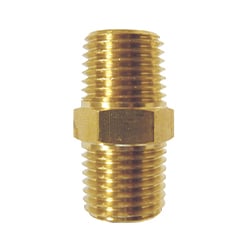
Threaded Adapter Tightening
An adapter is a fitting with one end designed for a compression connection and the other with a male or female thread.
- Proceed with the installation of the compression end, as outlined above.
-
To tighten the threaded end, the use of PTFE tape (or another suitable thread sealant) is recommended.
-
Leave one thread turn uncovered (without tape) at the end to prevent contamination of the piping system with tape fragments.
- Hand tighten first, then complete tightening with a wrench, following the turns chart below.
|
|
|
|---|


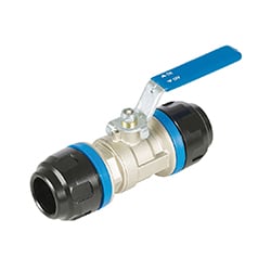
Compact Connection Fitting Tightening
Tools Required for Tightening of Compact Connection Fittings:
|
|
|
|
|
|
|---|


1. Verify proper alignment of the components before tightening.
|
Ensure proper alignment of the components before tightening to prevent leaks or internal damage.
Important reminder
|
|
|---|

2. Tighten gradually
For compact connection fittings with v-clamp:
-
Position the clamp correctly around the fitting.
-
Ensure the fitting and the pipe are perfectly aligned before tightening.
-
Gradually tighten the clamp, strictly following the recommended torque of 25 Nm.
-
Use a torque wrench with a hex socket to achieve precise and even tightening.

For compact connection fittings with flanges:
|
|
|---|

3. Always replace the seal after any loosening
-
To ensure a proper seal, the sealing gasket must always be replaced after any loosening or repositioning of a compact connection fitting.
-
Always ensure you have a spare supply of seals on site.
|
|
TECHNICAL TIP The use of FKM (fluoroelastomer) seals for aluminum fittings is strongly recommended in compressor rooms. In this environment, components are often exposed to high temperatures, significant thermal variations, as well as oils, lubricants, and chemical vapours generated by compressor operation. Using standard NBR seals may lead to premature degradation, leaks, and system failures. |

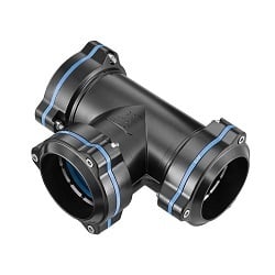
Bypass Saddle Tee installation (Depressurized System)
Tools Required to Install Bypass Saddle Tees:
 |
|
|
|
|
|---|


Note: The drill bits are specifically designed to prevent damage to or perforation of the back wall of the pipe, unlike conventional drilling tools. They feature an integrated stop that prevents drilling completely through the pipe during the operation.
Torque Reference Table

Steps
|
|
1. POSITION THE BYPASS SADDLE TEE
Adjust the bypass saddle tee to the desired position using the double markings in the pipe
|
|
2. MARK THE POSITION
Place the saddle tee in the desired position, then use a marker to draw a vertical line perpendicular to the horizontal line (already marked on the pipe).
|

|
3. TURN THE SADDLE TEE
Rotate the saddle tee 180° so that it aligns with the mark on the pipe.
|
|
4. PIPE DRILLING
Insert the drilling tool into the guide to drill the pipe. |
|
|
Check the drill hole and remove any aluminum shavings using the deburring tool (08.590). |
|
5. TIGHTEN THE SADDLE TEE
Reposition the tee to its original position and tighten the M8 bolt to the recommended torque |


Demonstration – Installing the Saddle Tee
|
If these instructions are printed, scan the QR code to access the video. |
|---|

Bypass Saddle Tee installation (Pressurized System)
Tools Required to Install Bypass Saddle Tees in a Pressurized System:
|
|
|
|
|---|
Torque Reference Table
Steps
|
|
1. POSITION THE SADDLE TEE
Position the bypass saddle tee at the desired location and tighten the M8 bolt to the recommended torque.
|
|
2. INSTALL THE DRILLING TOOL
Open the valve. Screw the drilling tool onto the valve. |
|---|---|---|---|
|
|
3. PIPE DRILLING |
|
4. CLOSE THE VALVE
Unscrew the drilling tool from the valve. |


Maintaining the Drilling Tool

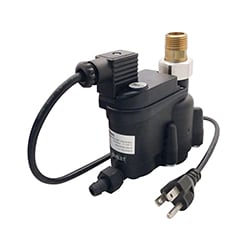
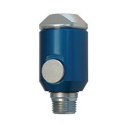
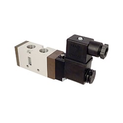
Pneumatic Pilot Valve Installation
Connect the pneumatic valve to the remote pilot by connecting the two Ø 4 PA tubes, following the “PILOT PRESSURE” and “CLOSING PORT” markings indicated on each component.
|
|
|


|
|
TECHNICAL TIP
To protect the piping and equipment from shocks during the opening of the remotely operated valve, it is recommended to install a flow control valve on the “Closing Port” line, near the control unit. This allows for a gradual opening over 3 to 5 seconds instead of a sudden opening in 0.5 seconds. |

System Testing and Commissioning
Warning Before Pressurization
-
The installer must comply with applicable standards and Topring installation guidelines.
-
Improper assembly of pipes and fittings may result in significant residual risks, including:
- Release of pressurized air or nitrogen due to connection failure caused by improper tightening.
- Release of pressurized air or nitrogen due to damage to the piping caused by impact.
- Release of pressurized air or nitrogen caused by excessive pressure, as the maximum allowable pressure is 232 PSI (16 bar).
System Pressurization
PRESSURIZATION MUST BE CARRIED OUT IN TWO STAGES
1. Perform a preliminary test by gradually increasing the pressure up to a maximum of 43.5 PSI (3 bar) and maintain it for at least 5 minutes. This allows for the identification of any leaks or irregularities in the system and the necessary corrections to be made. It will also help remove any remaining aluminum debris from the system.
2. Then increase the pressure gradually and steadily, at a rate of 14.5 PSI (1 bar) every 5 seconds, until the operating pressure is reached.
Pressurization Check
-
Once the desired pressure is reached, it must remain stable (with no significant drop) for at least 10 minutes.
-
After the first 48 to 72 hours, check all connections and ensure that all nuts remain properly tightened.
|
|
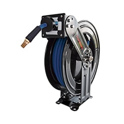
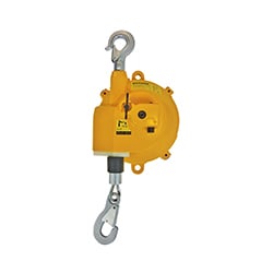
WARNING The piping system must never support loads other than its own weight, nor be subjected to external movements other than those caused by normal thermal expansion of its components. When setting up workstations, flexible hoses must be connected using properly secured hose reels or distribution blocks to isolate the piping from the weight and movement of tools. All work must be carried out on a depressurized system (or on a section that has been depressurized using a ball valve or a lockable safety valve). |
Legal Notice and Limitation of Liability
LIABILITY OF ALL BUYERS AND/OR USERS
In addition to carefully reading the Topring design guide, product guidelines, system and/or network (hereinafter referred to as « Topring Product(s) »), purchasers and/or users of a Topring Product that involves compressed air must inquire, prior to its use, about the health and safety risks associated with compressed air. Buyers and/or users acknowledge that by purchasing and using a Topring Product, they understand and accept that he or she is solely responsible for the installation, identification, maintenance, and use of the Topring Product, as well as the configuration of any system or network that uses a Topring Product. Subject to the limits of public policy as expressed in the law, buyers and/or users assume any risk and liability that may arise from loss, damage or injury caused by the improper installation, identification, maintenance and/or use of a Topring Product, or caused by a misconfiguration of any system or network using a Topring Product, to the extent to completely and entirely exonerate Topring , as well as its subsidiaries and affiliated corporations (hereinafter referred to as « Topring »). Buyers and/or users must take into consideration, among other factors, the regulations in force, the type use of any Topring Product, preventative measures, as well as the particular nature of the premises or location, and the activities or operations that take place. By purchasing a Topring Product, and subject to the limits of public policy expressed in the law, you hereby acknowledge and agree that Topring cannot be held liable for any damages whatsoever (including damages caused by loss of profits, business interruption or loss of information or otherwise) arising from the improper installation, identification, maintenance and/or use of a Topring Product, or the improper configuration of any system or network that uses a Topring Product, or arising from the unfeasibility of such a configuration, installation, identification, maintenance and/or use.
Purchasers and/or users of a Topring Product are responsible for communicating with any person that may be concerned the extent of the risk, as well as any warnings and preventative measures relating to Topring Products, including but not limited to employees using one or more TOPRING Products.