
Machinery Directive (MD 2006/42/EC)
The manufacturer of the HoseGuard® Safety Valve (air fuse) is TRI-MATIC AG (http://www.tri-matic.ch/) which produces the Declaration of Conformity with the Machine Directive ("DM") 2006/42/EC reproduced below. According ta this statement, the HoseGuard® Safety Valve is a safety component authorized ta bear the "CE" marking and which meets the criteria of the MD 2006/42/EC, including the essential health and security requirements that apply ta it. TOPRING also provides a declaration of conformity of TRI-MATIC AG and a manual of installation, operation and maintenance in accordance with the provisions of DM 2006/42/EC, which is translated from the original German version. As a manufacturer, TRI-MATIC AG is solely responsible for compliance with DM 2006/42/EC.
Workplace safety
Employing an air fuse helps in meeting relevant requirements of legislation, directives and standards and in significantly increasing safety in the workplace.
IMPORTANT-Liability & Notes on use
The use of an air fuse for compressed air hoses (HoseGuard® Safety Valve) may vary from a buyer and/or user ta another. Therefore, TOPRING is not responsible for any misuse of the HoseGuard® Safety Valve. Any buyer, user or designer of the system(s) in charge of the project (hereinafter "User") is responsible for the use of the HoseGuard® Safety Valve and is required ta assess the risks, as well as ta establish the instructions for and applicable safety instructions for the intended use of the HoseGuard® Safety Valve in its compressed air system.
We recommend, among other things, that the User take into consideration all the possible disturbances or that are likely ta occur in any compressed air system considered, and that the User takes the appropriate safety measures ta avoid any risk of injury ta people or property.
ln addition ta carefully reading the user guidelines for the TOPRING product(s), system(s) and/or network(s) including the HoseGuard® Safety Valve (hereinafter referred ta as "TOPRING Product(s)"), purchasers and/or users of a TOPRING Product that involves compressed air accept and must inquire, prior to its use, about the health and safety risks associated with compressed air.
Buyers and/or users accept and acknowledge that by purchasing and using a TOPRING Product, they understand and accept that he or she is solely responsible for the installation, identification, maintenance, and use of the TOPRING Product, the configuration or design of a system or network using a TOPRING Product and the feasibility of his or her configuration or design involving any TOPRING Product. Subject ta the limits of public policy as expressed in the law, buyers and/or users accept and assume any risk and liability of all loss, damage or injury caused, as the case may be, by the improper installation, identification, maintenance and/or use of a TOPRING Product, by the improper configuration or design of a system or network using a TOPRING Product and by the unfeasibility of his or her configuration or design involving any TOPRING Product, ta the extent ta completely and entirely exonerate TOPRING, as well as its subsidiaries and affiliated corporations (hereinafter referred ta as "TOPRING"). Buyers and/or users accept and must take into consideration among other factors, the regulations in force, the use of any TOPRING Product, preventative measures, as well as the particular nature of the premises or location, and the activities or operations that occur therein.
By purchasing a TOPRING Product, and subject ta the limits of public policy expressed in the law, you hereby acknowledge and agree that TOPRING cannot be held liable for any damages whatsoever (including and without limiting the foregoing any loss of profits or damage from business interruption or loss of information or otherwise) arising from the improper installation, identification, maintenance and/or use of a TOPRING Product, the improper configuration or design of a system or network using a TOPRING Product and the unfeasibility of his or her configuration or design involving any TOPRING Product.Purchasers and/or users of a TOPRING Product accept and are responsible for communicating with any person that may be concerned the extent of the risk, as well as any warnings and preventative measures relating ta TOPRING Products.
Purpose of use
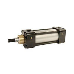
The air fuse is intended ta prevent pipes and hoses from being flung and whipped about in case plastic pipes or hoses burst. This is to prevent persons from being injured or machines from being damaged.
Operating principle
The operating principle of the air fuse for compressed air is:
General description of operation
|
|
The air supply enters at P1. The air flow passes by the plunger (1) and flows through the seat. The flow is slowed down by the longitudinal grooves (2) on the top side of the plunger. If the flow rate is tao high, the air cannai pass the plunger fast enough and presses il against the spring (3) towards the seat (4). The closing points are indicated by the diagrams on the respective data sheet. If the flow rate exceeds this value, the air supply is blocked automatically. Attention should be paid to the closing point, which varies for different pressures. |
|---|

Prohibited gases and liquids
Under no circumstances may the air fuse be employed as an air fuse for dangerous, taxic or easily flammable gases or any liquids such as but not limited to: Explosive or inflammable gases, flammable liquids, taxic or highly taxic gases, all liquids no matter what danger level
Conditions of use
These air fuses are intended solely for use in industrial compressed air systems. They may be used only in situations in which the specifications on the product label concerning upper and lower limit values for pressure and temperature are not exceeded. Please verify the technical data in the relevant product specification sheets.
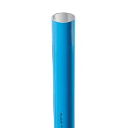
- To prevent confusing various gases during use, pipes with compressed air have to be colour-coded (e.g. blue).
- Additionally the maximum and minimum temperature specifications need to be observed and maintained.
- The air fuse may not be used in potentially explosive atmospheres.
- Any time work is ta be done on the system, il must be reliably depressurised (and secured by a lock) and a check must be made that there is actually no more pressure applied to the air fuse. Suitable persona! protective equipment must be worn (safety goggles, hearing protection, possibly gloves and protective clothing).
- The air fuse may only be installed in a system that is depressurised.
- The air fuse must not be removed. This is ta prevent the air fuse from being installed faultily and thus eliminating the protection from being available.
- An air fuse without product label may not be used or installed. If this is the case, please contact the manufacturer.
- The air fuse may not be employed in applications which require 100% of the available airflow. These are for example SAND BLASTERS and CONTAINER FILLERS (the air fuse is flow rate-regulated and cannot determine the difference between the maximum flow rate and the rupture of a hose or pipe).
The choice of air fuse must be made by consulting the data sheet containing the closing flow rate charts and by contacting a Topring technical advisor. All available technical information does not replace a test run under actual operating conditions. The air system should only be pressurized after rigorous testing of the valve's operation.
-
Selecting the right size of the air fuse for your application is of prime importance.
-
The flow rate has ta be sufficient for normal operation and in case a hose or pipe ruptures, the air fuse must trigger and close.
-
If the flow rate is too low, the air fuse does not close.
-
The proper air fuse needs ta be determined based on tests.
-
Observe the Function test for this (see Operation)
- The air fuse closes if the corresponding flow rate is reached with a tolerance of+/- 1 o %.
The following are relevant for selecting the size (dimensioning) of the air fuse
- The pressure at the air fuse (P1)
- The air consumption of the tool, at which pressure
- The inner diameter of the hose
- The length of the hose lines
- The size of the inlet valve and the quick coupling of the system
To select the proper air fuse for the hose or plastic pipe to be protected, the corresponding tables and charts with the closing points and specifications can be referred to below
The following values are used as ‘reference values’ for minimum hose diameters: 1/4"=6 mm / 3/8"=10 mm /1/2"=13 mm / 3/4"=16 mm /1"=19 mm
Air fuses also have different closing points at different pressures. Detailed specifications on that can be found below.
|
|
|
|---|---|
|
|
|
 |
 |
 |
 |
 |
 |
 |
 |
 |
 |
 |
 |
 |
 |
 |
 |
 |
 |


Example for determining the right air fuse
-
The maximum air consumption of the tool and the required pressure are critical for determining the right HoseGuard®.
-
If the air consumption of the tool is not known, il needs ta be measured. Theoretical specifications are insufficient and may lead ta malfunctions.
-
With the flow rate value and the closing point table, the right HoseGuard® Safety Valve can then be determined.
-
As a rule of thumb, the air fuse should be able ta handle at least 20 % more flow than a tool needs for normal operation.
-
Note: There are some tools that have a greater air consumption during start-up than during normal operation. Default specifications must always be checked.
Values for the example:
Air consumption of the tool = 800 NI/min
Pressure P1 at the HoseGuard® Safety Valve = 7 bar
Air fuse 3/8"
Airflow rate for closing (+ - 10%)

The table serves as an example and the values indicated can deviate tram actual values.
-
The air fuse 3/8" allows for about 1000 NI/min air at a pressure of 7 bar before il closes; its closing point lies therefore at 1000 NI/min. ln this example we therefore have a reserve of 200 NI/min by which the value of the closing is higher than the consumption of the tool.
- It is absolutely necessary to test whether this reserve is sufficient. If for example an air consumption of 1800 NI/min is needed, the 3/8" air fuse CANNOT be used, because the closing point lies below the flow rate of the tool. The tool could therefore not be operated.
Important: Where applicable, different tools may require different air fuses. An air fuse that has been configured for an air nailer gun with 500 NI/min cannot be used for a blow gun that consumes 2000 NI/min of air. After selecting an air fuse with a diameter that adequately ensures the safety aspects, the parameters and functions of the system need ta be checked as described under Function test (see OPERATION).
- Installation and maintenance of the air fuse have ta be carried out by qualified personnel.
- An air fuse may not be mounted in areas that can be exposed ta shocks.
- Dropping the air fuse must be avoided, as this can damage il and lead ta malfunctions later.
- The pipes have ta be free of rust and dirt particles.
- The air has ta be dried and conform ta air quality ISO 8573 1 class 5. Otherwise the function of the air fuse may be limited or the service life may be shortened.
- Before installing the air fuse, il needs ta be checked whether the air fuse is suitable for the designated purpose.
- The following data is necessary for that: the pressure applied to the air fuse, the air consumption of the consumer as well as the hose's inner diameter and ils length.
- A connection or quick coupling that has a wrong dimension may also possibly have a critical influence on improper functioning.
- For more information on this subject, see the section HOW TO CHOOSE THE CORRECT AIR FUSE.
- To avoid damage, the entire system needs ta be depressurised when the air fuse is installed.
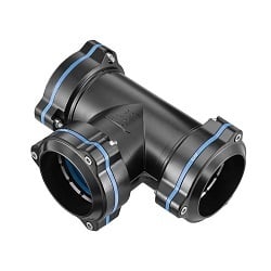
- The air fuse must always be connected to a stationary, permanent piping for compressed air supply (pipes, connection pieces etc.).
- If the air fuse is installed upstream from a valve, a quick coupler or similar component, then the inner diameter of the valve or the quick coupler needs to be larger than or equal to the inner diameter of the hose.
- It needs ta be ensured that the air fuse is installed in the correct direction of flow. This is indicated by arrows on the housing and the label.
- Air fuses without a label or with an illegible label must not be installed.
- A faultily installed or faultily dimensioned air fuse will not function properly. The result of this may be that the whipping about of the hose is not prevented.
- Even if all specifications on the graphs are observed, it is absolutely essential to conduct a function test with the actual configuration.
- Observe the points set out in the Function test (OPERATION) and Prohibited gases and liquids (SAFETY INFORATION).
Important notes on installation
The illustrations showing improper installations X will always lead ta faulty functioning or the complete failure of the air fuse.
|
The air fuse should not be installed at the end of flexible hoses. |
|
|---|---|
|
The air fuse has to be mounted to the end of a rigid line. Only the hose after the air fuse is protected. |
|
|
The flow direction must be observed; otherwise no closing function is possible. |
 |
|
The inner diameter at the inlet of the air fuse has to equal at least that of the outlet diameter. . |
 |
|
Only one tool may be protected per air fuse |
 |
|
An over dimensioned air fuse does not protect a small pressure hose. |
 |
|
Tools that consume more air than the closing point of the air fuse cannot be used or will have their operation limited. |
 |


Important: Each air fuse can only protect one tool and one hose, forming a single unit.
- If an air fuse is used for another tool, it is essential to determine beforehand whether it is suitable for this tool and whether the tool's air consumption is below the closing point of the air fuse. If this is not the case, the anti-whiplash valve will close too early, making it impossible to work.
- If any changes are made to the pipes (length/diameter) or to the connections on a pipe, it is absolutely essential to carry out a new functional check (see OPERATION).
- Always ensure that the flow of compressed air supplied does not decrease, due to a clogged filter for example. If this were the case, the air fuse could no longer reach its closing point.
Function Test
Before the air fuse is put into service for the first time, it should be tested according to the following instructions (in accordance with the functional check). This is the only way to ensure that the air fuse closes properly.
Procedure
- Are the inlet and outlet thread clean and free of rust, and is the internal piston (if visible) also clean?
- Can the piston be moved easily from the inlet side with a firm tap, and does it readily return to its initial position?
- Is the external surface of the air fuse free of damage or cracks?
- Is the air fuse's label still legible, and does the printed arrow match the actual flow direction?
- Has the air fuse been installed correctly and in accordance with the installation manual?
- Connect a compressed-air tool (or any pneumatic device) and switch on the compressed-air supply.
- If the system operates normally, switch off the compressed-air supply again.
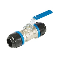
- Remove the tool or device and replace it with a ball valve. The ball valve MUST be firmly secured and closed (e.g., clamped in a vise).
- Verify that all connections are correct and tight.
- Slowly restore the compressed-air supply.
- The air fuse will open after a short delay. Once the hose pressure reaches its maximum, fully open the ball valve.
- The air fuse will close and shut off the compressed-air supply.
- A small amount of compressed air will continue to bleed, ensuring proper automatic reset.
If the air fuse does not function properly or does not close, each function needs ta be checked individually - as shown on the illustration under INSTALLATION>Important notes on installation to ensure proper operation.
ln case the desired results are not achieved, it needs ta be checked whether the air fuse is suited for the designated hose, tool and the fixtures used. Precise air consumption specifications of the manufacturer are often not available, which is why flow rate tests must be carried out ta determine how high the flow rate actually is. Likewise the couplers used have a critical influence on proper functioning.
Operating instructions
- The air fuse may not be operated in areas that can be exposed ta shocks.
- Before being put ta use the first lime, the air fuse needs ta be tested according ta the specifications of the Function test (see 2.2). Only then can il be guaranteed that the closing function of the air fuse is ensured.
- If filtered compressed air is used (ace. ta ISO 8573-1 class 5), the system needs ta be checked every six months in accordance with the procedure described in the Function test (see 2.2).
- If the air is heavily soiled or saturated with water vapour and does not conform ta class 5, then a premature wear of the components is very likely. The oxidation of the aluminium housing can jam the plunger and thus cause the air fuse ta fail.
- The first indication of this is a white, powdery or flaky surface on the aluminium. When such indications are detected, we urgently recommend exchanging the air fuse.
- Please note that after activating the air fuse a slight delay of the pressure increase occurs before the system becomes fully operational again. This reactivation lime may differ depending on the size of the air fuse and the hose dimensions and lengths used.
- Likewise, when a quick coupler is reconnected or the ball valve / shutoff valve is opened again, the air fuse closes again; il opens again automatically soon thereafter. Il features a small opening that permits a minor amount of air ta escape and reactivate the automatic reset. This bore hale must not be closed under any circumstance; otherwise, the air fuse cannot function fully and will not open after closing.
- Use the air fuse exclusively for its intended purpose. Il must never be misused as a safety, reduction, regulating or stop valve. This list is not exhaustive.
Label
The specifications on the product label provide information on the conditions under which the HoseGuard® Safety Valve (air use) functions faultlessly.
For this reason, these values must be complied with; the upper and lower limits of the operational pressure and temperature in particular must not be exceeded.
The label displayed below is a sample label. Your product label may therefore have specifications which deviate from those shown. Only the label on the respective product is authoritative and these values must be observed.

- The air fuse is maintenance free and therefore only needs a regular function test according ta the function test instructions (OPERATION<Function test).
- This has to be carried out every 6 months at the latest and be documented.
- If compressed air is used that does not at least meet the standards of ISO 85731 class 5, the maintenance intervals need ta be shortened accordingly.
- Additionally, the air fuse needs to be dismantled from the piping system so that the inner surfaces and parts of the air fuse can be viewed.
- Under no circumstances may the air fuse be disassembled. This ensures that the components are not inserted erroneously into the housing, causing a faulty function of the air fuse
- If the aluminium parts show a white, powdery or flaky surface, this surface oxidation can result in the plunger becoming jammed and thus cause the protective component ta fail. ln this case, we recommend that the
air fuse should definitely be replaced. - You should also check the reason why the pneumatic lines are saturated with water or water vapour and initiate measures ta rectify this.
Important
Can the piston be moved easily from the inlet side with a firm tap and does it go back to its initial position without a problem? If not, the air fuse definitely needs to be replaced.
Once the visual check has been completed without any indication of problems, the air fuse may be reinstalled into the piping system.
Be sure that the correct direction of flow is complied with. Conclude by carrying out the FUNCTION TEST according to the instructions (OPERATION>Function test).