
Serial Number Location

Warnings
- Read instructions first.
- This digital inflator is only intended for measuring, inflation, and deflation of vehicle tires with air. Any other use of this product is considered improper.
- Use only compressed, filtered, oil-free air.
- Do not exceed the inflators maximum pressure rating.
- Do not drop the device. It may influence the functionality and the calibrated accuracy.
- Warranty not applicable for devices that have been used improperly, taken apart, modified or with missing or broken parts or with traces of internal clogging caused by anti-puncture products, anti-corrosive fluids or ballast water. Must only be repaired by authorized personnel. Do not break the seals to maintain warranty and calibration.
- Best practice is short fill intervals followed by pressure reading.
- The pressure value may fluctuate for a few seconds after inflation/deflation and will then stabilize due to a natural thermodynamic phenomenon.
- Do not lock the trigger in inflation position unattended—risk of explosion!
- Do not inflate tires filled with water for ballast, anti-puncture products or anti-corrosive agents.
- Keep safe distance from tires during inflation. Stand outside the trajectory of any potential explosion.
- Adjust the tire pressure according to the tire and vehicle manufacturer’s recommendations
- Weather, temperature, altitude, and heat friction (from driving) affects the tire pressure. A rule of thumb is that an increase of 10 °C in ambient temperature will increase the tire pressure by 1.5 psi. For maximum accuracy carry out the inflation in the temperature range from 15° to 25 °C.
- The device recalibrates automatically to zero when connected to atmospheric pressure at the shutdown to improve accuracy. Carry out an initial inflation sequence and let the device shutdown if the device has changed environment (location/temperature) or not has been used for a long period. When calibrating the device must not be connected to a pressure source (e.g., tire). If so “Er.C” is written in display upon shutdown.
- Do not direct air at yourself or bystanders. Wear safety glasses and hearing protection (users and bystanders). Do not inflate when not connected to a tire. The hose can be tossed uncontrollably around.
- This product contains a button battery when put into use. If swallowed, a lithium button battery can cause severe or fatal injuries within two hours. Keep batteries out of reach of children. If you think batteries may have been swallowed or placed inside any part of the body, seek immediate medical attention.
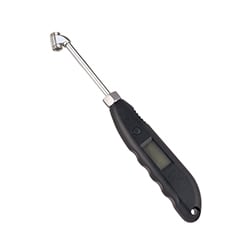
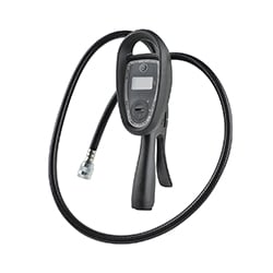
Operation
To turn on gauge, press 1x on ON/UNIT button
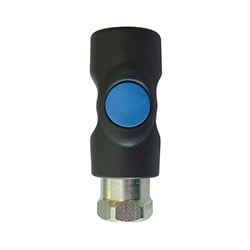
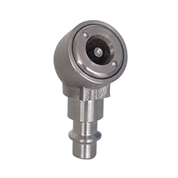
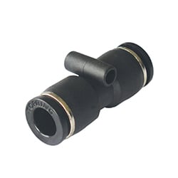
Push the connector onto the valve to connect to tire. Pull the sleeve to disconnect.
To read pressure, connect turned-on gauge to tire (images 3 and 4).


Changing Units
Press the ON/UNIT button for 4 seconds to access the Change Unit mode (image 1).

The gauge will use the unit on which the Change Unit mode stopped (image 5).

Changing The Battery
The low battery indicator appears when the battery needs to be changed (image 1).


To Calibrate
If the device has changed environment (location/temperature) or not has been used for a long period, carry out an inflation sequence and let the device shutdown to calibrate. The device recalibrates automatically to zero (at atmospheric pressure) at the shutdown to improve accuracy. When calibrating, the device must not be connected to a pressure source (e.g., tire).
Troubleshooting P.HI/P.LO
If maximum pressure was exceeded, P.HI will appear on the screen. Disconnect the unit from the tire (image 1).
If the pressure falls below minimum pressure, P.LO will appear on the screen. Disconnect the unit from the tire (image 1A).

To clear P.HI or P.LO error messages, remove and reinsert the battery (images 2 and 3).

Calibration Error
If unit is turned off while connected to a pressure source (tire), Er.C will appear on the screen. Carry out an inflation sequence and let the device shutdown clear the Er.C error message.

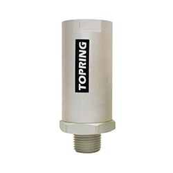
Shut-Off

Operation
Preparing the tire valve
- Remove the tire valve cap.
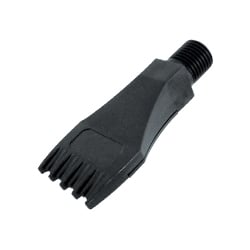
- Attach the air chuck:
- Depress the clip-on air chuck lever.
- Firmly press the chuck onto the tire valve stem.
- Release the lever and ensure there are no air leaks.
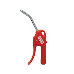
Inflate/deflate
- Press the grip to inflate.
- Press the grip halfway to deflate.
Inflator gauge Operation
Power On
- Press the on/unit/light button to turn on the inflator gauge.
- The inflator gauge will automatically turn off after 90 seconds of inactivity.
Backlit display:
- When the inflator gauge is on, press the on/unit/light button to turn on the backlit display for easy reading in low light conditions.
- The backlit display will automatically turn off after 5 seconds.
- The backlit can only be activated by pressing the on/unit/light button.
Change of unit (PSI/BAR/KPA/KGF)
- Press the on/unit/light button for more than 3 seconds.
- Then, press the on/unit/light button briefly to select the desired unit.
- The selected unit will be the default for future use.
Low battery indicator:
- A flashing low battery signal will appear in the top left corner, reminding the user to change the batteries. Use AAA batteries.
Measuring range: 7-174 PSI (0-12 BAR)
Reading accuracy: 0.1 PSI (0.01 BAR)
Maximum inlet pressure: 232 PSI (16 BAR)
Warning
To avoid the risk of personal injury (eyes, face, or skin), DO NOT direct the compressed air stream at any person.
Calibration Certificate
- This inflator gauge has been calibrated in its normal working position on test equipment with accuracy traceable to National Standards.
- According to: 86/217/EEC
- Allowable tolerances:
+/- 1.2 PSI up to and including 58 PSI comparable to: +/- 0.08 BAR up to and including 4 BAR
+/- 2.3 between 58 PSI and 145 PSI inclusive comparable to +/- 0.16 BAR between 4 BAR and 10 BAR inclusive
+/- 3.6 PSI at greater than 145 PSI comparable to +/- 0.25 BAR at greater than 10 BAR
Operating instructions
- Remove tire valve cap.
- With clip-on air chuck lever depressed, firmly press chuck onto tire valve stem and release lever, ensure that there are no air leaks.
- Press the grip to inflate, press the grip half-way to deflate.
Specifications
Measuring Range: 7-180 PSI (0.5-12 BAR).
Reading Accuracy is 2 PSI (0.1 BAR).
Maximum Inlet Pressure 218 PSI (15 BAR).
Warning
To avoid the risk of personal injuries (the eyes, face or skin)DO NOT direct the compressed air stream at any person.
Calibration certificate
This inflator gauge has been calibrated in its normal working position on test equipment with an accuracy that is traceable to National Standards. According to: 86/217/EEC
Allowable tolerance:
+/- 1.2 PSI up to and including 58 PSI or +/- 0.08 BAR up to and including 4 BAR
+/- 2.3 between 58 PSI and 145 PSI inclusive or +/- 0.16 BAR between 4 BAR and 10 BAR inclusive
+/- 3.6 PSI at greater than 145 PSI or +/- 0.25 BAR at greater than 10 BAR
Operation
Prepare the Tire Valve:
- Remove the tire valve cap.Attach the air chuck:
- Depress the clip-on air chuck lever.
- Firmly press the chuck onto the tire valve stem.
- Release the lever and ensure there are no air leaks.
Inflate/Deflate/Measure Pressure
|
|
For pressure measurement, place the grip in position (A). To deflate, press the grip halfway (B). To inflate, press the grip fully (C). |
|---|

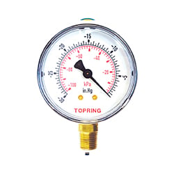
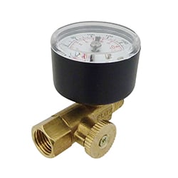
Gauge Reset Instructions
- Although the gauges are adjusted at the factory, it may occasionally be necessary to reset the needle to zero.
- Always set up on a solid surface for safe operation.
- Ensure the hose is no longer under pressure before proceeding.
CAUTION: Make sure the hose is no longer under pressure before proceeding.
1) Locate the adjustment screw:
- The adjustment screw for the needle is located at the base of the dial, on the right side (A).
- Use a 5/16’’ wrench to slightly loosen the nut, no more than 1/2 a turn (B).
- Use a small flat screwdriver to adjust the screw at the center (C).

2) Adjust the needle position:
- If the needle is past zero, turn the adjustment screw clockwise (A).
- If the needle does not reach zero, turn the adjustment screw counterclockwise (B).

3) Fine-tune the adjustment:
- Proceed in small increments until the needle is in the center of the zero zone (A).
- Do not adjust the other screw under the red cap as this will affect the calibration of the gauge (B).

4) Test the gauge:
- After any adjustment, test the gauge by measuring a known pressure to confirm proper operation.
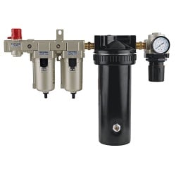
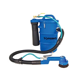
Operation

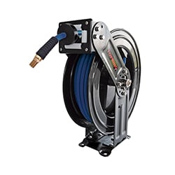
Connect the air supply:
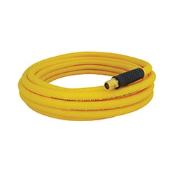
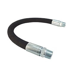
- Attach the air supply hose (4) to the gauge.
Inflation and pressure checking:
- Attach the air chuck (1) to the tire valve by pressing the lever (2) on the air chuck.
- Firmly grasp the gauge to read the pressure.
To inflate:
- Press the control lever (3) until air is emitted.
- Release the lever and read the pressure.
- Repeat this operation until the desired pressure is shown on the dial of the pressure gauge.
To deflate:
- Release the control lever (3).
- Press the deflation button (5) with your thumb until air is released.
Warning
- Do not drop the gauge. If dropped, check the calibration.
- Avoid connecting the supply hose (4) to a pressure above 12 Bar/174 Psi.
- Avoid connecting the air chuck (2) to sources with a pressure higher than indicated on the dial of the pressure gauge.
- Use the gauge only with air and nitrogen.
- Do not use the gauge in any other manner than described in these operating instructions.