

General Instructions
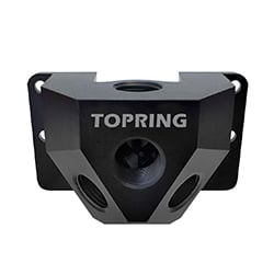
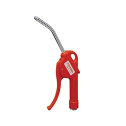
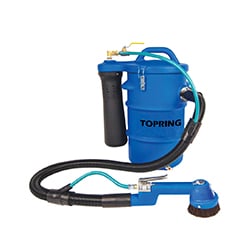
The TOPRING Cold Air Gun is designed for spot cooling applications and delivers optimal performance with minimal maintenance. The unit is factory set to utilize 70% of the incoming compressed air for cooling purposes.
This system contains no moving parts, offering long-term durability when used with clean, dry air. To maintain peak performance and prevent damage, users must ensure proper air supply, filtration, and installation procedures.
Cold Air Gun No. 68.270/272 includes a 15 SCFM generator installed. Other SCFM generators are included and may be swapped to adjust the airflow. Using a higher SCFM generator increases airflow volume but raises the output air temperature by approximately 8–10°F per step up from a 10 SCFM generator. Regardless of the generator, 70% of the inlet air will be used for cold air discharge.
Installation
Air Line Preparation
- Blow out existing air lines or hoses prior to installation to eliminate built-up dirt or oil.
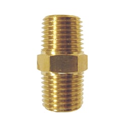
- Carefully apply thread sealant or tape to pipe fittings to avoid introducing debris into the product’s internal orifices.
Air Filtration
Compressed air often contains condensed water vapor, Oil droplets and/or rust and dirt
To avoid clogging the small orifices inside the Cold Air Gun:
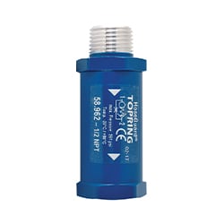
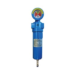
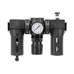
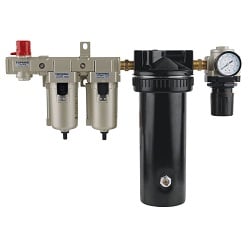
- Install a 5-micron air filter (e.g., model 50.140) to remove 99% of contaminants like water, dirt, and rust.
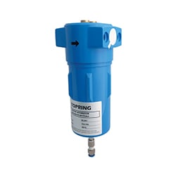
- For oil-contaminated air, add a coalescing filter (e.g., model 50.945) to remove oil droplets and vapor (effective down to 0.01 micron).
Cold Air Gun Installation
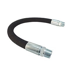
- Use the included Cold Air Gun with a compatible air line and fittings.
- Ensure all connections are tight and free from leaks.
- Install the Cold Air Gun as close as possible to the application point for optimal performance.
Operation
Air Supply Specifications
- Operate the Cold Air Gun within a line pressure range of 70–90 PSI.
- Pressure alone is not sufficient — a proper air volume (SCFM) must also be available.
Recommended Line Sizes
To ensure sufficient pressure and volume, use:
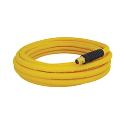
- Up to 10 ft: 3/8" pipe or 1/2" hose
- Up to 20 ft: 1/2" pipe or 3/4" hose
- Up to 50 ft: 3/4" pipe or 1" hose
Generator Adjustment
The Cold Air Gun includes interchangeable generators:
- Use higher SCFM generators to increase air volume.
- Each increase in SCFM raises the cold air temperature by 8–10°F.
- Always maintain the O-ring when replacing generators to ensure proper sealing.
Warning
TO AVOID UNPREDICTABLE SYSTEM BEHAVIOR THAT CAN CAUSE PERSONAL INJURY AND PROPERTY DAMAGE:
- Disconnect electrical supply (when necessary) before installation,servicing, or conversion.
- Disconnect air supply and depressurize all air lines connected to this product before installation, servicing, or conversion.
- Operate within the manufacturer’s specifi ed pressure, temperature, and other conditions listed in these instructions.
- Medium must be moisture-free if ambient temperature is below freezing.
- Service according to procedures listed in these instructions.
- Installation, service, and conversion of these products must be performed by knowledgeable personnel who understand how pneumatic products are to be applied.
- After installation, servicing, or conversion, air and electrical supplies (when necessary) should be connected and the product tested
for proper function and leakage. If audible leakage is present, or the product does not operate properly, do not put into use.
- Warnings and specifications on the product should not be covered by paint, etc. If masking is not possible, contact your local representative for replacement labels.
Maintenance
The TOPRING Cold Air Gun requires minimal maintenance due to its solid-state design.
However, the following steps will help ensure continued performance:
- Regular Filter Maintenance: Check and replace air filters to maintain clean air supply.
- Air Supply Monitoring: Periodically inspect for signs of contamination such as rust, oil, or water.
- Ice Prevention: If the air inside the unit reaches 32°F (0°C), water vapor can freeze and clog internal orifices. In this case:
- Use an air dryer rated at 35°F dew point or lower to remove moisture before it enters the gun.
Cleaning the Unit
If performance drops due to contamination:
- Disassemble the unit.
- Clean all parts thoroughly.
- Reassemble and tighten the cold end cap to reseat the generator.
Changing the Generator (Model No. 68.270/272)
To swap the generator:
- Use a single-point spanner wrench to remove the cold end threaded cap (1).
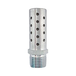
- Unscrew and remove the cold end muffler assembly (2).
- Unscrew and remove the cold end cap (3) using a 1" hex.
- Remove the stationary generator (4) and O-ring (5) by hand.
- Insert the desired SCFM generator and reinstall the O-ring.
- Tighten the cold cap securely to seat the new generator.

Warning
FAILURE OR IMPROPER SELECTION OR IMPROPER USE OF THE PRODUCTS AND/OR SYSTEMS DESCRIBED HEREIN OR RELATED ITEMS CAN CAUSE DEATH, PERSONAL INJURY AND PROPERTY DAMAGE.
This document and other information from The Company, its subsidiaries and authorized distributors provide product and/or system options for further investigation by users having technical expertise. It is important that you analyze all aspects of your application, including consequences of any failure and review the information concerning the product or systems in the current product catalog. Due to the variety of operating conditions and applications for these products or systems, the user, through its own analysis and testing, is solely responsible for making the fi nal selection of the products and systems and assuring that all performance, safety and warning requirements of the application are met.
The products described herein, including without limitation, product features, specifications, designs, availability and pricing, are subject to change by The Company and its subsidiaries at any time without notice.
Installation
Piping Preparation
- Purge existing lines or pipes before installation to remove any dirt or oil buildup.
- Carefully apply thread sealant or pipe tape to the fittings to prevent debris from entering the product.
Air Filtration
Compressed air often contains water vapor, oil droplets, and/or rust or solid particles.
To prevent internal orifices of the cabinet cooler from clogging:
- Install a 5-micron air filter (e.g., model 50.140) to remove 99% of contaminants such as water, dirt, and rust.
- If oil is present, add a coalescing filter (e.g., model 50.945) to remove oil droplets and vapors (down to 0.01 micron).
Ducting
- The 8 ft. of vinyl ducting connects to the cold end of the Control Cooler inside the electrical cabinet.
- The ducting allows more efficient use of the cold air by routing the cold air to the hottest spots.
- By punching a hole in the tube by the hot spot, the cold air cools more effectively, restricting the high temperature increase of the particular hot control.
- The open end of the ducting should be placed at the bottom of the cabinet. As the cold air exits from the tubing. It rises as it heats and provides more even cooling through-out the cabinet.
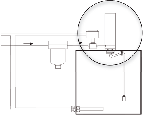
Mounting
- The illustration in Figure 1 shows how the cabinet cooler should be installed.
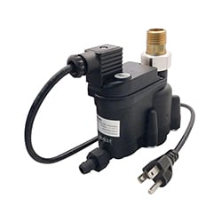
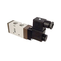
- The diagram also shows the thermostat and solenoid valve.
- Keep in mind that the thermostat has a wide temperature range, and even a 1/16 turn of the screw can change the temperature by 50°F.
- For this reason, the factory calibration at 90°F should not be changed unless under extreme conditions.
- The cabinet cooler requires a standard ¾" electrical knockout. The thermostat requires a standard ½" knockout for installation.
Operation
Compressed Air Line Diameter- You can register a pressure of 70–90 psi without having a sufficient air volume (SCFM).
- To ensure both pressure and volume allow for efficient operation, the tubing should be 3/8" (pipes – 1/2") for installations within 10 ft of the main manifold.
- If the unit is located within 20 ft, use 1/2" tubing and 3/4" pipes. For installations within 50 ft, use 3/4" tubing and 1" pipes.
Cooler Operation
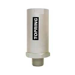
- The TOPRING cooler is equipped with a 25 SCFM generator.
- It provides 1,800 BTU of cooling capacity, which is enough to cool a 6 ft x 6 ft x 2 ft cabinet to 90°F when the ambient temperature is up to 140°F, as long as 80 PSI is available and the compressed air entering the cooler is dry and at 75°F.
- When 80 PSI is not available, the potential cooling BTUs must be reduced by 25% at 60 PSI and by 50% at 40 PSI.
- TOPRING’s stainless steel control cooler is factory-set to deliver the maximum cooling power required to maintain your control panel at the desired temperature.
- At 80 PSI, 17.5 SCFM (70% of 25 SCFM) of cold air will be blown into the panel via the Vortex tube, providing 1,800 BTUs of cooling.
- The cooler’s thermostat is very useful for controlling compressed air usage, as it only activates when cooling is needed.
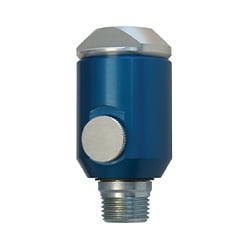
- The solenoid valve will automatically release hot air from the cabinet, maintaining a positive pressure inside the cabinet equivalent to an 8-inch water column.
- This automatic release of air through the solenoid valve allows you to block open conduit entrances, louvers and air leaks.
- A sealed cabinet is also more efficient, as the cold air only enters the cabinet and does not escape into the atmosphere, increasing the effectiveness of compressed air use.
Maintenance
Filter Checks
Check and replace filters regularly to ensure clean compressed air. This will maintain the cooler’s performance and prevent clogs.
Cooler Maintenance
The TOPRING cooler has no moving parts and does not require frequent maintenance. However, debris, water, or oil may occasionally affect performance. In such cases:
- Depressurize the system.
- Open the product, clean the parts, and reassemble, making sure to properly close the cold end cap to seal the generator.
Freeze Prevention
If the air temperature inside the cooler reaches 32°F (0°C), water vapor can freeze and block the generator orifices. Use an air dryer set to -35°F to lower the dew point and prevent this issue.
Warning
TO AVOID UNPREDICTABLE SYSTEM BEHAVIOR THAT CAN CAUSE PERSONAL INJURY AND PROPERTY DAMAGE:
- Disconnect electrical supply (when necessary) before installation,servicing, or conversion.
- Disconnect air supply and depressurize all air lines connected to this product before installation, servicing, or conversion.
- Operate within the manufacturer’s specifi ed pressure, temperature, and other conditions listed in these instructions.
- Medium must be moisture-free if ambient temperature is below freezing.
- Service according to procedures listed in these instructions.
- Installation, service, and conversion of these products must be performed by knowledgeable personnel who understand how pneumatic products are to be applied.
- After installation, servicing, or conversion, air and electrical supplies (when necessary) should be connected and the product tested for proper function and leakage. If audible leakage is present, or the product does not operate properly, do not put into use.
- Warnings and specifications on the product should not be covered by paint, etc. If masking is not possible, contact your local representative for replacement labels.
FAILURE OR IMPROPER SELECTION OR IMPROPER USE OF THE PRODUCTS AND/OR SYSTEMS DESCRIBED HEREIN OR RELATED ITEMS CAN CAUSE DEATH, PERSONAL INJURY AND PROPERTY DAMAGE.
This document and other information from The Company, its subsidiaries and authorized distributors provide product and/or system options for further investigation by users having technical expertise. It is important that you analyze all aspects of your application, including consequences of any failure and review the information concerning the product or systems in the current product catalog. Due to the variety of operating conditions and applications for these products or systems, the user, through its own analysis and testing, is solely responsible for making the fi nal selection of the products and systems and assuring that all performance, safety and warning requirements of the application are met.
The products described herein, including without limitation, product features, specifications, designs, availability and pricing, are subject to change by The Company and its subsidiaries at any time without notice.