
Warning
- Read carefully and understand all instructions before operating.
- Failure to follow the safety rules and other basic safety precautions may result in serious personal injury.
- Save these instructions in a safe place and on hand so that they can be read when required.
General Safety Rules
WARNING: The warning, cautions, and instructions discussed in this instruction manual cannot cover all possible conditions or situations that could occur. It must be understood by the operator that common sense and caution are factors which cannot be built into this product,
but must be supplied by the operator.
Hose Reel Safety Precautions
- Use proper eye protection when assembling and using this hose reel.
- Keep children away from the work area.
- Personal injury and/or equipment damage may result if proper safety precautions are not observed.
- Ensure that reel is properly installed before connecting input and output hoses.
- Bleed fluid/ gas pressure from system before servicing reel.
- Before connecting reel to supply line ensure that pressure does not exceed maximum working pressure rating of reel.
- Remember, even low pressure is very dangerous and can cause personal injury or death.
- If a leak occurs in the hose or reel, remove system pressure immediately.
- Ensure that reel, hose, and equipment being service are properly grounded.
- If reel ceases to unwind or rewind, remove system pressure immediately.
- Do not pull or jerk on hose.
Installation
- Prior to mounting the hose reel, ensure that the supply line pressure does not exceed the maximum working pressure of the hose reel.
- Unpack and inspect reel for damage. Turn by hand to check for smooth operation. Check for completeness.
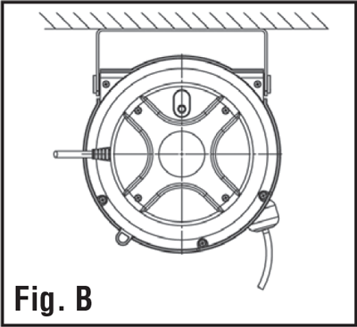
- For overhead ceiling mounting : Install reel at most 10 feet/ 3m above the floor.
- You will need to purchase appropriate hardware for mounting your new reel.
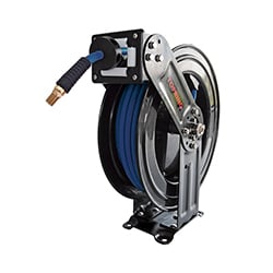
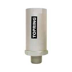
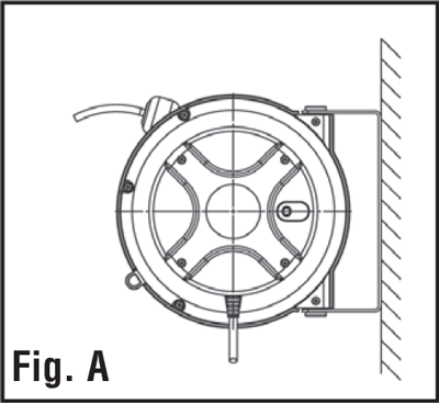
- The reel base has three 8.5 mm (21/64 ) drilled holes for mounting on a suitable flat surface (Fig. A wall / Fig. B ceiling).
- Using the three holes in the base, mount the reel in the desired location. Be sure to use appropriate hardware and tighten securely.
- Apply Teflon tape or pipe sealant to supply line threads, attach to reel inlet and tighten. The other end incoming line can now be connected to desired supply source.
- Apply Teflon tape or pipe sealant to outlet fitting on reel hose, and then attach to desired tool, or nozzle. Check connection for leakage; also check hose reel for correct operation. See : Operation section.
- If hose stopper adjustment is required, pull hose from reel and allow latching at desired length. Loosen stopper bolts, and slide stopper to a position close to the hose guide. Tighten stopper bolts, and unlatch the reel.
Operation
- Check reel for correct operation by slowly pulling out the hose. A clicking noise will be heard every half revolution of the drum.
- To latch the reel, pull out the hose and allow it to retract after hearing the first second or third click.
- To unlatch, slowly pull out the hose until the clicking noise stops, then le the hose retract until the hose Stopper rest against the hose guide.
- If necessary, adjust spring tension on reel by adding or removing wraps of hose from spool, one wraps at a time, until desired tension is obtained, at most 4 to 5 circles.
- Wind the hose to increase and unwind it to decrease tension.
Maintenance
- Make sure the hose is in proper working order.
- Clean the hose with a cloth dipped in warm water to remove dirt, or deposits and ensure correct rewinding.
- Do not use detergents or solvents which could prove incompatible with cable-winder materials.
- Dismantling of the unit by unskilled personal could prove hazardous; the risk involved mainly concern the preloaded springs.
Limited Warranty
- The manufacturer warrantees this hose reel against defects in material and craftsmanship, for a period of 24 months from date of purchase, but not including hose and O-ring parts.
- Manufacturer’s liability is limited to replacement or repair of defective material within the warranty period, when returned freight prepaid to the distributor or their designated service depot.
- The warranty does not cover damage caused by accident, misuse or faulty installation.
- The reel must be installed and maintained in compliance with the instructions.
General Safety Rules
Please read and understand all instructions. Failure to follow the safety rules and other basic safety precautions may result in serious injuries.
Hose Reel Safety Precautions
- Use proper eye protection when assembling and using the hose reel.
- Keep children away from the work area.
- Personal injury and/or equipment damage may result if proper safety precautions are not observed.
- Ensure that the reel is properly installed before connecting input and output hoses.
- Bleed fluid and/or air pressure from system before servicing the reel.
- Before connecting the reel to the supply line, ensure that the pressure does not exceed the maximum working pressure rating of the hose and reel. Remember, even low pressure is very dangerous and can cause personal injury or death.
- If a leak occurs in the hose or reel, remove system pressure immediately.
Hose Reel Installation
- Unpack and inspect the reel for damage. Turn by hand to check for smooth operation.
- Prior to mounting the hose reel, ensure that the supply line pressure does not exceed the maximum working pressure of the hose. Refer to the specifications of your hose maximum usage pressure.
- The reel base has four drilled holes for mounting on a suitable flat surface. Secure into place using mounting bolts in the fixture (bolts not included). Position the reel on the floor, wall or ceiling (see mounting options graphic for mounting options). For overhead ceiling mounting, install reel at least 10 feet above the floor.
- The reel is supplied with a rotating hose guide roller bracket. The bracket position may be changed depending on the reel mounting position. If bracket position needs to be changed, do the following:
- Pull the hose from the reel and let reel latch.
- Remove bolts that attach the guide roller bracket to the support post. Rotate guide roller bracket to correct position.
- Replace bolts and tighten stopper bolts, and then unlatch the hose
inside the reel.
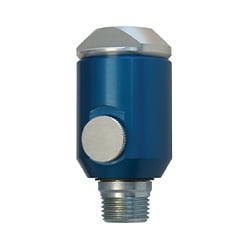
- Apply PTFE sealant to supply line threads, attach to reel inlet and tighten. If a hose has been supplied with reel, apply PTFE sealant to outlet fitting of the hose reel, and then attach to desired air tool. Check connection for leakage; also check hose reel for correct spring tension (see Adjustment for Spring Tension section).
- IMPORTANT: Depending on where the hose reel is installed (eg at the ceiling, 15 feet from the ground) it is necessary to unwind manually the hose at the desired length (see Adjustment for Spring Tension section / to remove wraps).
Adjustment for spring tension
WARNING Use extreme caution; reel under tension. Remove all tension before servicing. Hazards or unsafe practices may result in personal injury or product damage. Always disconnect and lock out compressed air before servicing. Avoid releasing lock mechanism.
If necessary, adjust spring tension on reel by adding or removing wraps of hose from spool, one wrap at a time, until the desired tension is obtained. Add wraps to increase the tension. Remove wraps to decrease the tension.
To add wraps
Pull out the hose leaving 15 feet on the spool. Make sure the locking mechanism is engaged. Turn the hose manually around the spool, making it shorter.
WARNING When adding wraps of hose, do not wind more that 2 wraps at the time to avoid exceeding the spring capacity. Add just enough wraps of hose to achieve the desired tension. Damage to the winding mechanism will result if the spring is over-tensioned.
To remove wraps
Pull out 4 to 5 feet of hose. Bring the hose bumper back closer to the reel without activating the rewind mechanism. Hose should now be loose enough to remove wraps from the reel manually.
Service
User servicing of the reel is limited to replacing input hose only. Failure to do so can result in person injury and/or equipment damage.
MOUNTING OPTIONS
Floor

Ceiling

Wall

Dimensions (mm)
