Compressed air is a critical source of energy in industrial environments. It is considered the fourth most used utility after electricity, natural gas, and water. Understanding the fundamentals of compressed air allows you to use it safely, efficiently, and with maximum performance.
The Importance of Compressed Air and Cost Management
Compressed air offers several advantages: tools that are 2 to 3 times lighter than their electric equivalents, reduced worker fatigue and injuries, reliable operation with no risk of electric shock in humid environments, clean energy, adjustable pressure, and no risk of fire or explosions.
Compressed air accounts for approximately 10% of industrial electricity consumption. Proper planning and optimization of a compressed air system help reduce operational costs while improving overall performance.
Cost Breakdown of a Compressed Air System Over 10 Years
| Category | Percentage |
|---|---|
| Energy | 80% |
| Initial investment (parts and equipment) | 10% |
| Maintenance | 10% |
Energy consumption represents the majority of total system costs over a 10-year period.
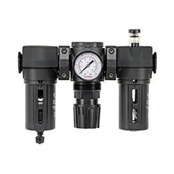
A performance-driven design (properly sized piping, efficient filters, high-quality hoses and fittings) combined with systematic maintenance (repairing leaks, reducing excessive pressure, replacing clogged filters) can generate 10 to 20% energy savings. Even greater savings are possible with improved compressor control and increased storage capacity.
The 7 Essential Fundamentals of Compressed Air
1. What Is Compressed Air? → The Source
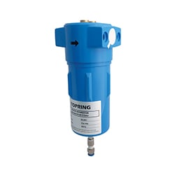
Compressed air is atmospheric air pressurized to a higher level using a compressor. This process reduces its volume, increasing its pressure. In practical terms, 7 volumes of ambient air are compressed into 1 volume of untreated compressed air. Since ambient air contains pollutants (dust, viruses, agricultural and industrial contaminants), proper air treatment is essential before use.
Composition of Ambient Air
| Component | Percentage |
|---|---|
| Nitrogen | 78% |
| Oxygen | 21% |
| Other gases | 1% |
2. What Is Pressure? → The Force
Pressure represents the potential energy stored in the system, similar to electrical voltage. It is measured in pounds per square inch (PSI or PSIG).
- Static pressure: uniform pressure present when the system is charged but no air is flowing.
- Dynamic pressure: the pressure available at the point of use while air is flowing and the tool is working. It is always lower than the compressor’s pressure due to system restrictions.
In a poorly designed system, a large gap between static and dynamic pressure can damage tools and reduce efficiency.
3. What Is Airflow? → The Volume
Airflow is the volume of air moving through the system over time. The most common measurement is SCFM (Standard Cubic Feet per Minute).
Pressure provides force, while airflow ensures the system can maintain that pressure during continuous use.
- Rotary tools (grinders) require high continuous airflow.
- Percussive tools (nailers) consume small bursts of air per cycle.
4. What Is Over-Pressurization? → The Efficiency Killer
Over-pressurization occurs when system pressure exceeds the actual requirements of pneumatic tools—typically between 30 and 90 PSI.
TRUE OR FALSE: Increasing pressure improves tool performance? FALSE. Poor tool performance is almost always caused by insufficient airflow, not insufficient pressure. Excessive pressure increases leaks, reduces tool life, and forces the compressor to work harder.
A system running 14.5 PSI higher than required increases energy costs by approximately 7%—without improving performance. It also accelerates wear on the compressor and increases leakage rates.
5 & 6. What Are Pressure Drops and Excessive Drops? → The Losses
A pressure drop is the difference between the pressure at the receiver tank and the pressure measured at the point of use. It is caused by restrictions in the system: piping, filters, hoses, connectors, and fittings.
- Acceptable pressure drop: 10% or less between the tank and the tool is considered normal in an efficient system.
Increasing compressor pressure to compensate for pressure loss is a common and costly mistake. Every 2 PSI added to the system increases energy consumption by roughly 1%. It also increases tool wear, compressor strain, and leakage volume.
7. How to Prevent Pressure Losses → Optimization
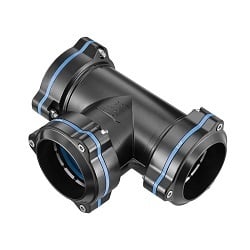
Proper system planning and appropriate component selection are essential for minimizing pressure losses. A closed-loop design provides more uniform distribution compared to a straight-line system.
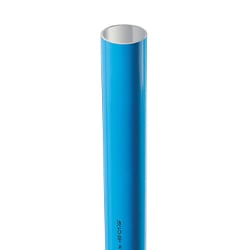
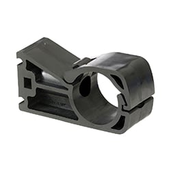
Piping Materials and Diameter
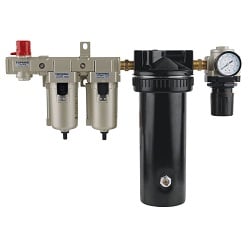
Use aluminium or nylon piping instead of traditional steel. These materials prevent corrosion, offer a smooth interior surface, and improve airflow. Pipe diameter must be selected based on system length and required airflow.
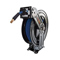
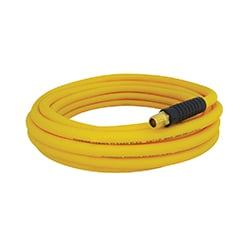
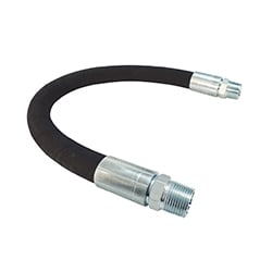
Flexible Hoses and Airflow Capacity
The inside diameter (ID) of flexible hoses has a direct impact on airflow (SCFM).
| Hose Size | Relative Airflow Capacity |
|---|---|
| 1/4 in. I.D. | 1X |
| 3/8 in. I.D. | 2.25X |
| 1/2 in. I.D. | 4X |
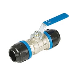
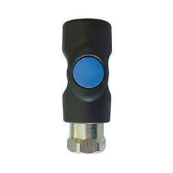
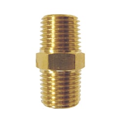
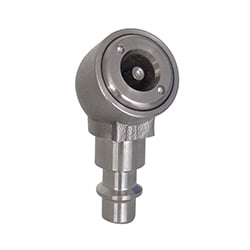
Quick-Connect Couplers
The design and internal profile of quick-connect couplers determine the available airflow to the tool. Restricted openings cause choking and pressure loss. High-flow couplers (high-SCFM) significantly improve performance.
| Coupler Diameter | Airflow Range |
|---|---|
| 5.5 mm | 24–37 SCFM |
| 7 mm | 60–70 SCFM |
| 7.8 mm | 50–80 SCFM |
Leak Repair
The average industrial facility loses 20 to 50% of the compressed air it produces due to leaks. Ideally, total leakage should be kept under 10%. Replacing worn couplers, damaged hoses, and defective components is essential for controlling operating costs.
Estimated Annual Cost of Leaks (based on 8760 hours at 90 PSIG)
| Leak Diameter | Annual Cost |
|---|---|
| 1/64 in | $46 |
| 1/8 in | $2,970 |
| 1/2 in | $47,500 |
Balancing System Capacity
The compressor must supply airflow equal to or greater than the system’s average demand. A properly sized receiver tank helps handle peak demand and ensures the compressor runs efficiently, reducing wear and extending service life.