
Important Note
- All product codes, photos and technical specifications can be found in the AIR LINE catalogue.
- Please refer to our AIR LINE design guide available here, before proceeding with the installation.
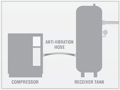
- The AIR LINE piping system must never be connected directly to the compressor outlet.
- An anti-vibration hose and a receiver tank must be installed before the AIR LINE piping system to protect the system from excessive heat and the effects of thermal variations.
Installation
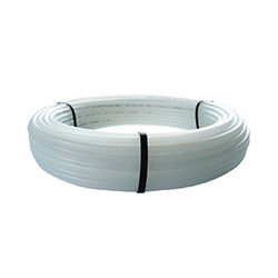
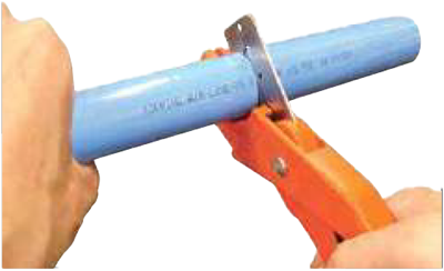
1. Cut the pipe
- Use pipe cutter 36.100. (We reccommend the use of this model as it allows effortless straight, even and accurate cutting of nylon pipes up to 36 mm (1-13/32 in) O.D.)
- The cut must be straight and perpendicular to the pipe, a maximum of ≤ 7° is tolerated for cuts.
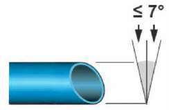
WARNING: To ensure a propel seal, the pipe must be smooth and free of scratches, impacts or distortions.
2. Verify the cut
Make sure the edges are not sharp and that there are no burrs, either inside or outside the pipe. The Pipe surface must not be sanded or scratched.

3. Clean the pipe and fitting
- Eliminate all residue, dirt and dust inside the pipe to avoid any potential equipment problems.
- It is strongly recommended to clean the ends of the pipe and the inside of the fitting with a clean cloth.

4. Mark the pipe
- To avoid air leaks, determine the the insertion depth of the pipe into the fitting based on the chart below.
- You can mark the insertion depth directly on the pipe.

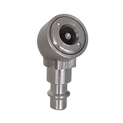
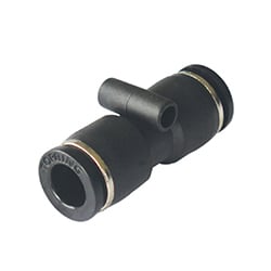
5. Pipe and fitting assembly
15 and 22 mm
- The installation is very simple, easy to modify and no special equipment required.
- For a high-performing and long-lasting system, you only need to take a few simple precautions.
WARNING: Lubricants, grease, and oil must not be used for the pipe and fitting connection. the presence or use of lubricants may result in improper sealing and pipe connection.

Easy 3-step connection |
|
|---|---|
Step 1Push in to pipe stop.
|
|
Step 2Pull to make sure that pipe is secure. Test the system before use.
|
|
Step 3To disconnect, ensure the system is depressurized. Push the collet towards the fitting and remove the pipe. The fitting can be reused.
|
 |


28 mm
WARNING: Lubricants, grease, and oil must not be used for the pipe and fitting connection. the presence or use of lubricants may result in improper sealing and pipe connection.

Easy 3-step connection |
|
|---|---|
Step 1Push in to pipe stop.
|
|
Step 2After inserting the pipe, turn screw cap approx 1/4 turn. This locks the collet in place and reduces lateral and sideways
movement of the pipe. |
|
|
Step 3
To disconnect, turn the screw cap 1/4 turn, push in the collet and remove the pipe. The fitting and pipe can be reused.
|
 |


6. Visually check that the fitting is properly tightened.

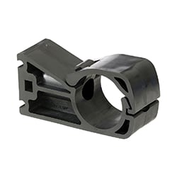
7. Install the mounting clips for the pipes and spacers.
Main line
- In order to eliminate the possibility of line bending, it is mandatory to follow the mounting clips instructions.
- The mounting clips must be installed at a maximum of 15 cm, on each side of the fitting, and the chart below indicates the maximum distance between each mounting clip.
| Pipe Diameter | Maximum distance between each mounting clip |
|---|---|
| 15 mm | 90 cm |
| 22 mm | 120 cm |
| 28 mm | 150 cm |
Example with a 28 mm pipe

Drops
- The mounting clips installation for drops must be done after the system is pressurized to allow the effects of thermal variations to take place.
- Thereby, the drops will be positioned at a 90° to the horizontal piping.
Maintenance
Here is a list of recommended checks and controls by TOPRING:
- Review the status of the installation on an annual basis.
- Check the tightening of the nuts.
- In the event of an impact, check the condition of the pipe and replace any damaged parts.
- Check for air leaks.
Warning: Any type of intervention must be carried out on a depressurized system or depressurized section (using a quarter turn ball valve or a lockable safety valve).
Warnings
CHECKING BEFORE PRESSURIZING / RESIDUAL RISK
Without respecting the safety information and requirements provided in this document, an inadequate assembly of the system can result in:
- Under pressure fluid ejections, in case of disconnection caused by inadequate tightening.
- Under pressure fluid ejections, in case of damage to the pipe caused by shocks.
- Under pressure fluid ejections, if the operating pressure is higher than 145 PSI (10 BAR) at 23 ºC and 100 PSI (6.9 BAR) at 70 ºC.
When identified, defective parts must be repaired immediately.
PRESSURIZING (TWO PHASES)
- Run a preliminary test by gradually raising the pressure to a maximum of 43.5 PSI (3 BAR). This will allow the operator to identify leaks or faulty connections and make the necessary corrections. Gradual pressurization will also remove all the aluminum residue in the system.
- Gradually and continuously increase the pressure, 14.5 PSI (1 BAR) every 5 seconds, until it reaches the working pressure.
PRESSURIZING VERIFICATION
- Once the working pressure has been reached, maintain the working pressure for at least 10 minutes (slight dips are tolerated).
- After the first 48 to 72 hours, check all seals and verify that nuts are secured.
THE PIPING SYSTEM SHOULD NEVER SUPPORT LOADS OTHER THAN ITS OWN WEIGHT, OR BE EXPOSED TO MOVEMENT OTHER THAN THE NORMAL EXPANSION OF ITS COMPONENTS. WHEN PLANNING THE LAYOUT OF A WORKSTATION, FLEXIBLE HOSES SHOULD BE CONNECTED THROUGH STURDILY ATTACHED HOSE REELS OR MANIFOLDS TO ISOLATE PIPING FROM TOOL WEIGHT AND MOVEMENT.
Liability of All Buyers and/or Users
In addition to carefully reading the TOPRING design guide, product guidelines, system, and/or network (hereinafter referred to as "TOPRING Product(s)"), purchasers and/or users of a TOPRING Product that involves compressed air must inquire, prior to its use, about the health and safety risks associated with compressed air.
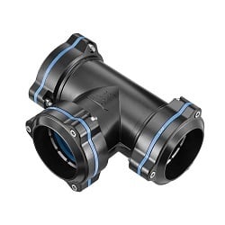
Installation
The water trap tee convertor will stop condensed water within the air line main circuit from entering the vertical take off spurs. It is however important that the air line main be installed with the correct
fall, and water drain points be regularly vented.
- The rigid 28 mm nylon tubing must be cut square and be free from burrs.
- The shorter spigot should be pressed into the tube end.

- The tube and Convertor should be firmly inserted into the central port of the tee. Full insertion is required to correctly locate the Convertor

By turning the screw cap by approximately 1/4 turn (2 clicks can be heard) the collet is locked into place and further compression of the O-ring on the pipe is achieved.