
Series 49- Instruction Manual
Table of Contents
1. General Rules
2. Standard and High Temperature Refrigerated Dryers
General Instructions
Technical Specifications, Replacement Parts and Repair Kits
To consult the technical specifications, replacement parts list and repair kits available for your product, please visit the product page by searching for the product number (SKU) in the main menu's search bar.
Warning
Read this manual carefully before carrying out any operations on the dryer.
The installation of the dryer and all operations involving it must be performed in conformity with the regulations in force concerning electrical and personal safety.
Personal injury and/or property damage may result if proper safety precautions are not observed.
Intended Use
The dryer is built to dry the compressed air for industrial use. The dryer cannot be used in premises where there is a risk of fire or explosion or where work is carried out which releases substances into the environment which are dangerous with regard to safety (for example: solvents, inflammable vapours, alcohol, etc.).
Specifically, the dryer cannot be used to produce air to be breathed by humans or used on direct contact with foodstuffs. These uses may be allowed if the compressed air produced is filtered by means of an accredited filtering system.
Product not suitable for outdoor installation.
The dryer must be used only for the purpose for which it was specifically designed. All other uses are to be considered incorrect and therefore unreasonable. Topring cannot be held responsible for any damage resulting from improper, incorrect or unreasonable use.
Important
- The following operation, service and repair manual has been designed to give the operator/user a full understanding of the operational aspects of the dryer.
- Topring highly recommends that any operator familiarise themselves with the following information in this manual before operating the dryer to avoid injury and damage.
To avoid unpredictable system behaviour that can cause personal injury and property damage:
- Disconnect the electrical supply before installation, servicing or conversion.
- Disconnect the air source and depressurize all lines connected to this product before installation, servicing, or conversion.
- Operate within the specified pressure, temperature and other conditions listed in these instructions.
- Service according to procedures listed in these instructions.
- Installation, service, and conversion of these products must be performed by knowledgeable personnel who understand how pneumatic products are to be employed.
- After installation, servicing, or conversion, air and electrical supplies should be connected and the product tested for proper function and leakage. If audible leakage is present, or the product does not operate properly, do not put it into use.
- Warnings and specifications on the product should not be covered by paint, etc. Otherwise, please contact TOPRING for a replacement label.
Failure or improper selection or improper use of the products and/or systems described herein, or related items can cause death, personal injury and property damage. This document and other information from The Company, its subsidiaries and authorized distributors provide product and/or system options for further investigation by users having technical expertise. It is important to analyze all aspects of your application, including the consequences of any failure and review the information concerning the product or systems in the current product catalogue. Due to the variety of operating conditions and applications for these products or systems, the user, through its own analysis and testing, is solely responsible for making the final selection of the products and systems and assuring that all performance, safety, and warning requirements of the application are met. The products described herein, including without limitation, product features, specifications, designs, availability and pricing, are subject to change by The Company and its subsidiaries at any time without notice.
Symboles de précaution
|
|
Warning. Possible hazards, ensure you have full knowledge of the task being carried out. |
|---|---|
 |
Warning. Dangerous electric voltage. |
 |
Warning. Hot parts. |
 |
Consult Topring. |
Handling
The product must be transported while securely packaged:


Cutting metal strapping is a dangerous operation.
After removing the packaging, ensure that the product is intact and that there are no visibly damaged parts.

If you are in doubt, do not use the product and contact Topring for technical assistance.
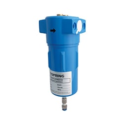
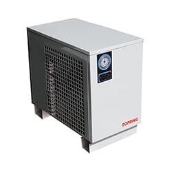
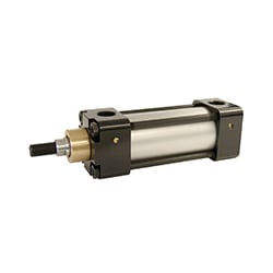
Refrigerated Air Dryer
General Characteristics
The non-cycling dryer is a chilling machine with direct expansion and dry evaporator. The air to be dried is sent to the heat exchanger in which the water vapour present is condensed; the condensate gathers in the separator and is discharged outside through a highly efficient zero air loss condensate drain.
Flow Diagram
The gaseous refrigerant coming from the evaporator (4) is sucked by the refrigeration compressor (1) and it is pumped into the condenser (2). This allows condensation of the refrigerant, with the help of the fan (3); the condensed refrigerant passes through the dewatering filter (8), and it expands through the capillary tube (7) and goes back to the evaporator where it produces the refrigerating effect. Due to the heat exchange with the compressed air which passes through the evaporator against the stream (10), the refrigerant evaporates and goes back to the compressor for a new cycle.
The circuit is equipped with a bypass system for the refrigerant; this intervenes to adjust the available refrigerating capacity to the actual cooling load. This is achieved by injecting hot gas under the control of the valve (9), which keeps constant the pressure of the refrigerant in the evaporator. This ensures the dew point never decreases below 0 °C (32 °F), in order to prevent the condensate from freezing inside the evaporator. The dryer runs completely automatically.
Models 49.201 to 49.227 and 49.271 to 49.292
 |
Number and name of the part 1- Refrigerant Compressor 2-Condenser 3-Fan 4-Evaporator 5-Demister Condensate Separator 6-Y-strainer 7-Expansion Capillary Tube 8-Dewatering Filter 9-Hot Gas Bypass Valve 10-Air-to Air Heat Exchanger 11-Dew Point thermometer 12-Condensate Drain |
|---|---|
Models 49.231 to 49.252
 |
Number and name of the part 1- Refrigerant Compressor 2-Condenser 3-Motor Fan 4-Evaporator 5-Demister Condensate separator 6-Y-Strainer 7-Expansion Capillary Tube 8-Refrigerant Filter 9-Hot Gas Bypass Valve 10-Air-to-Air exchanger 11-Dew Point Thermometer 12-Fan Control Pressure Switch 13-Condensate Drain |
|---|---|
Installation
Positioning
- After unpacking the dryer, put the machine into position on a sturdy horizontal surface.
- Ensure surface is capable of supporting the weight of the unit.
- The place of installation should be free of vibrations.
- Sufficient space around the dryer is required to allow maintenance and air flow. The minimum clearance around the dryer is 1.5 m (59 in).
- The place of installation must be dry, well ventilated, and free from dust. Blocked air circulation reduces the rate of dehumidification and the service life of the dryer.
- Do not place dryer on a surface that is contaminated by corrosive, acid, or alkali deposits; dryer will corrode.
- Do not install the dryer in corrosive or explosive environment. There should be no flammable products at the place of installation.
- The ambient temperature of the place of installation should be above 5 °C (41 °F) to prevent unit malfunction.
- The dryer should not have direct exposure to sun rays.
Electrical Connection
Only professionally skilled personnel may have access to the electric panel. Compliance with the local regulations concerning electrical work is fundamental for operator safety and for the protection of the machine.
- Switch off the power before opening the door of the electric panel.
- Check that the supply voltage is the same as the value indicated on the dryer data plate.
- Check the condition of the electrical line leads and ensure that there is an efficient earth lead.
- Ensure that there is a differential overcurrent protection device (not supplied) upstream of the dryer to protect against overcurrent.
- Refer to the electrical schematic and direct any questions to Topring customer support.
Compressed Air Connection
- Depressurize and lockout air pressure.
- Upstream pipes must be free of excessive dirt and liquids.
- It is recommended to install a bypass in order to facilitate servicing the dryer.
- Install the filter as close as possible to the dryer.
- The dryer should be isolated from the vibrations of the air compressor.
- The compressed air piping should follow the air flow direction in accordance with the inlet and outlet of the dryer. Assembling the piping in the wrong direction will cause the unit to malfunction.
- The compressed air piping should not rest directly on the dryer connections. It should be supported independently.
- Drainage of condensate must comply with the local regulations in force.
Start Up
Before starting the dryer, check:
- The connection to the compressed air piping is leak-free.
- The connection to the condensate drainage system in place.
- The power supply is adequate.
- Switch on the dryer.
- Run the dryer for 5 minutes prior to opening up the air inlet and outlet valves.
- After 5 minutes, slowly open the inlet valve to pressurize the dryer. If compressed air enters the dryer quickly, the pressure could damage parts or instruments.
- Test the condensate drain function by pressing the test button on the drain.
- Slowly open the outlet valve to the system.
- Always start the dryer before the air compressor starts running and stop it after the air compressor has been stopped. The dryer must be kept on during all the time the air compressor is running to ensure that the compressed air piping is free of condensates.
After switching off the dryer, wait at least 5 minutes before starting it again, in order to allow the pressure balancing.
Control Panel
Models 49.201 to 49.252
 |
Number an name of the part 1- Dew Point Indicator 2-Power Switch |
|---|---|
Models 49.271 to 49.292
 |
Number and name of the part 1- Digital Controller 2- Alarm Indicator 3- Compressor Indicator 4- Fan On Indicator 5- Power Indicator 6- Dew Point Indicator 7- Power Switch |
|---|---|
Icon
|
|
Off: No warning active On: Alarm warning. See Troubleshooting section. |
|---|---|
 |
Off: Compressor off Flash: Maintenance reminder. On: Dryer on |
 |
Off: Fan off Allumé : Fan on |

Maintenance
All models
The maintenance intervals are recommended for work environments that are not dusty and are well ventilated. For dusty environments, increase the frequency of controls.
Daily Maintenance
- Check that the condensate drain evacuates the condensed water.
- Check that there are no air leaks on the compressed air connections.
- Verify the compressed air temperature at the inlet and the ambient temperature are within operating parameters of the dryer specification.
Weekly Maintenance
Dirty or plugged condensate drain strainer will impact performance of the dryer and can lead to excessive moisture in the compressed air.
To clean the condensate drain strainer:
- Depressurize and lockout air pressure to dryer.
- Switch off the dryer and isolate from power source.
- Remove the cover panels.
Avoid hot parts.
Wait at least 5 minutes before starting the dryer again, in order to allow the pressure balancing.
Monthly Maintenance
Dirty or plugged condenser coils will impact performance of the dryer and can lead to overheating of the compressor and possible shutdown and/or damage of the dryer.
To clean the condenser:
- Switch off the dryer and isolate from power source.
- Remove the cover panels.
Avoid hot parts.
3. Clean the condenser using a vacuum cleaner, a brush or compressed air. Do not use water or solvents.
4. Ensure that the fins and the thin aluminum plate of the condenser do not get bent out of shape while cleaning.
5. Re-install the panels and follow the start-up sequence.
Wait at least 5 minutes before starting the dryer again, in order to allow the pressure balancing.
If the machine is to be scrapped, it must be disposed of according to the local regulations in force.
Special care needs to be taken regarding the refrigerant within the unit. It should not be released to the atmosphere. All refrigerants should be reclaimed by a properly certified refrigerant technician prior to the unit being scrapped
Technical Data
Models 49.201 to 49.227
 |
Number and name of the part 1- Refrigerant Compressor 2- Condenser 3- Fan 4- Evaporator 5- Condensate Drain 6- Hot Gas Bypass Valve 7- Refrigerant Filter 8- Expansion Capillary Tube |
|---|---|
| Model | Net weight kg (lbs) | L mm (po) | W mm (po) | H mm (po) | A Inlet | B Outlet | Max Pressure PSI (bar) | Min Inlet Air Temp °C (°F) | Max Inlet Air Temp °C (°F) |
| 49.201 - 49.202 | 19 (42) | 233 (9.17) | 550 (21.6) | 560 (22) | 1/2 (F)NPT | 1/2 (F)NPT | 232 (16) | 10°C (50°F) | 50°C (122°F) |
| 49.205 - 49.207 | 19 (42) | 233 (9.17) | 550 (21.6) | 560 (22) | 1/2 (F)NPT | 1/2 (F)NPT | 232 (16) | 10°C (50°F) | 50°C (122°F) |
| 49.211 - 49.212 | 20 (44) | 233 (9.17) | 550 (21.6) | 560 (22) | 1/2 (F)NPT | 1/2 (F)NPT | 232 (16) | 10°C (50°F) | 50°C (122°F) |
| 49.216 - 49.217 | 25 (55) | 233 (9.17) | 550 (21.6) | 560 (22) | 1/2 (F)NPT | 1/2 (F)NPT | 232 (16) | 10°C (50°F) | 50°C (122°F) |
| 49.221 - 49.222 | 27 (59) | 233 (9.17) | 550 (21.6) | 560 (22) | 3/4 (F)NPT | 3/4 (F)NPT | 232 (16) | 10°C (50°F) | 50°C (122°F) |
| 49.226 - 49.227 | 30 (66) | 233 (9.17) | 550 (21.6) | 560 (22) | 1 (F)NPT | 1 (F)NPT | 232 (16) | 10°C (50°F) | 50°C (122°F) |
| model | Rated Flow* SCFM | Refrigerant Gas | Power Supply v/Ph/Hz | Absorbed Power kW | Full Load Amps | Min Ambient Air Temp °C (°F) | Max ambient Air Temp °C (°F) |
| 49.201 - 49.202 | 15.3 | R-513A | 115/1/60 | 0.16 | 2.2 | 5°C (41°F)F) | 40°C (104°F)F |
| 49.205 - 49.207 | 21.4 | R-513A | 115/1/60 | 0.16 | 2.1 | 5°C (41°F)F) | 40°C (104°F)F |
| 49.211 - 49.212 | 30.6 | R-513A | 115/1/60 | 0.23 | 3.4 | 5°C (41°F)F) | 40°C (104°F)F |
| 49.216 - 49.217 | 45.8 | R-513A | 115/1/60 | 0.33 | 4.4 | 5°C (41°F)F) | 40°C (104°F)F |
| 49.221 - 49.222 | 55 | R-513A | 115/1/60 | 0.37 | 4.8 | 5°C (41°F)F) | 40°C (104°F)F |
| 49.226 - 49.227 | 76.3 | R-513A | 115/1/60 | 0.59 | 8.3 | 5°C (41°F)F) | 40°C (104°F)F |
*Rated flow capacity @ 100 psig, 35°C inlet, and 25°C ambient air temperature.

Models 49.231 to 49.252
 |
Number and name of the part 1- Refrigerant Compressor 2- Condenser 3- Motor Fan 4- Evaporator 5- Condensate Drain 6- Hot Gas Bypass Valve 7- Refrigerant Filter 8- Expansion Capillary Tube 9- Fan Switch |
|---|---|
| Model | Net Weight kg (lbs) | L mm (po) | W mm (po) | H mm (po) | A Inlet | B Outlet | Max Pressure PSI (bar) | Min Inlet Air Temp °C (°F) | Max Inlet Air Temp °C (°F) |
| 49.231 - 49.232 | 69 (153) | 310 (12.20) | 706 (27.79) | 994 (39.13) | 1 (F)NPT | 1 (F)NPT | 232 (16) | 10°C (50°F) | 50°C (122°F) |
| 49.236 - 49.237 | 66 (146) | 310 (12.20) | 706 (27.79) | 994 (39.13) | 1-1/2 (F)NPT | 1-1/2 (F)NPT | 188 (13) | 10°C (50°F) | 50°C (122°F) |
| 49.241 - 49.242 | 72 (159) | 310 (12.20) | 706 (27.79) | 994 (39.13) | 1-1/2 (F)NPT | 1-1/2 (F)NPT | 188 (13) | 10°C (50°F) | 50°C (122°F) |
| 49.246 - 49.247 | 75 (166) | 310 (12.20) | 706 (27.79) | 994 (39.13) | 1-1/2 (F)NPT | 1-1/2 (F)NPT | 188 (13) | 10°C (50°F) | 50°C (122°F) |
| 49.251 - 49.252 | 73 (161) | 310 (12.20) | 706 (27.79) | 994 (39.13) | 1-1/2 (F)NPT | 1-1/2 (F)NPT | 188 (13) | 10°C (50°F) | 50°C (122°F) |
| Model | Rated Flow* SCFM | Refrigerant Gas | Power Supply V/Ph/Hz | Absorbed Power kW | Full Load Amps | Min Ambient Air Temp °C (°F) | Max Ambient Air Temp °C (°F) |
| 49.231 - 49.232 | 91.6 | R-513A | 230/1/60 | 0.73 | 5.5 | 5°C (41°F) | 40°C (104°F) |
| 49.236 - 49.237 | 103.9 | R-513A | 230/1/60 | 0.76 | 5.3 | 5°C (41°F) | 40°C (104°F) |
| 49.241 - 49.242 | 132.9 | R-410A | 230/1/60 | 0.80 | 4.7 | 5°C (41°F) | 40°C (104°F) |
| 49.246 - 49.247 | 164.9 | R-410A | 230/1/60 | 0.81 | 5.3 | 5°C (41°F) | 40°C (104°F) |
| 49.251 - 49.252 | 195.5 | R-410A | 230/1/60 | 0.96 | 6.2 | 5°C (41°F) | 40°C (104°F) |
*Rated flow capacity @ 100 psig, 35°C inlet, and 25°C ambient air temperature.

Models 49.271 to 49.292
|
49.271 et 49.272 |
Number and name of the part 1- Refrigerant Compressor 2- Condenser 3- Motor Fan 4- Evaporator 5- Condensate Drain 6- Hot Gas Bypass Valve 7- Refrigerant Filter 8- Expansion Capillary Tube |
|---|---|
 |
Number and name of the part 1- Refrigerant Compressor 2- Condenser 3- Motor Fan 4- Evaporator 5- Condensate Drain 6- Hot Gas Bypass Valve 7- Refrigerant Filter 8- Expansion Capillary Tube |
 49.281 à 49.292
|
Number and name of the part 1- Refrigerant Compressor 2- Condenser 3- Motor Fan 4- Evaporator 5- Condensate Drain 6- Hot Gas Bypass Valve 7- Refrigerant Filter 8- Expansion Capillary Tube |

| Model | Net Weight kg (lbs) | L mm (po) | W mm (po) | H mm (po) | A Inlet | B Outlet | Max Pressure PSI (bar) | Min Inlet Air Temp °C (°F) | Max Inlet Air Temp °C (°F) |
| 49.271 - 49.272 | 26 (57) | 350 (13.78) | 500 (14.88) | 484 (19.05) | 3/4 (M)NPT | 3/4 (M)NPT | 232 (16) | 10°C (50°F) | 82°C (180°F) |
| 49.276 - 49.277 | 49 (108) | 460 (18.11) | 575 (22.63) | 789 (31.05) | 1/2 (F)NPT | 1/2 (F)NPT | 232 (16) | 10°C (50°F) | 82°C (180°F) |
| 49.281 - 49.282 | 76 (168) | 460 (18.11) | 575 (22.63) | 789 (31.05) | 3/4 (F)NPT | 3/4 (F)NPT | 232 (16) | 10°C (50°F) | 82°C (180°F) |
| 49.286 - 49.287 | 105 (231) | 460 (18.11) | 575 (22.63) | 1040 (40.95) | 1 (F)NPT | 1 (F)NPT | 232 (16) | 10°C (50°F) | 82°C (180°F) |
| 49.291 - 49.292 | 107 (236) | 460 (18.11) | 575 (22.63) | 1040 (40.95) | 1 (F)NPT | 1 (F)NPT | 232 (16) | 10°C (50°F) | 82°C (180°F) |
| Model | Rated Flow* SCFM | Refrigerant Gas | Power Supply V/Ph/Hz | Puissance absorbée kW | Full Load Amps | Min ambient Temp °C (°F) | Max ambient Temp °C (°F) |
| 49.271 - 49.272 | 25 | R-513A | 115/1/60 | 0.47 | 5.2 | 5°C (41°F) | 48°C (120°F) |
| 49.276 - 49.277 | 50 | R-404A | 115/1/60 | 1.0 | 11.4 | 5°C (41°F) | 48°C (120°F) |
| 49.281 - 49.282 | 75 | R-404A | 115/1/60 | 2.0 | 18.7 | 5°C (41°F) | 48°C (120°F) |
| 49.286 - 49.287 | 100 | R-404A | 115/1/60 | 1.9 | 17.5 | 5°C (41°F) | 48°C (120°F) |
| 49.291 - 49.292 | 125 | R-404A | 115/1/60 | 2.4 | 18.6 | 5°C (41°F) | 48°C (120°F) |
*Rated flow capacity @ 125 psig, 82°C inlet, and 35°C ambient air temperature.


Troubleshooting
All work must be carried out by professionally trained and licensed personnel and/or authorized service provider.
All models
| Issue | Possible Causes | Possibles Actions |
| 1. No compressed air passes through the dryer outlet. |
a) The evaporator piping is obstructed with ice. |
a) Turn off unit to thaw. Ensure room temperature is within limits before restarting the unit. |
| 2. Condensates present in the piping. |
a) The dryer is working outside its rated capacity. |
a) Ensure the flow rate, the room temperature, and the inlet air temperature at the dryer are within limits. |
| 3. The compressor head is very hot > 55 °C (131 °F), or motor cuts out on overload. |
a) The dryer is working outside its rated capacity. |
a) Ensure the flow rate, the room temperature, and the inlet air temperature at the dryer are within limits. |
| 4. The motor hums and does not start. |
a) You switched the machine off and on again without leaving enough time for the pressure balancing. |
a) Wait at least 5 minutes before starting the machine again. |
| 5. The dryer has stopped and does not restart even after a few minutes. | The overload protection has intervened. | Call for service. |
| 6. The compressor is very noisy. | Problems with internal mechanical parts or with the valves. | Call for service. |
Models 49.271 to 49.292
| Display | Alarm | Notes | Probable Causes | Possible Actions |

|
Dryer is working OK | n/a | n/a | |

|
Dryer is working OK | n/a | n/a | |

|

|
P1 Flashing | Fan control probe failed. | Call for service. |

|

|
P2 Flashing | PDP Temp probe failed. | Call for service. |

|

|
H2 Flashing, High PDP | a) Temperature exceeding limits. b) Refrigerant leak. |
a) Ensure the flow rate, the room temperature, and the inlet air temperature at the dryer are within limits. |

|

|
L2 Flashing, Low PDP |
a) Ambient temperature lower than limit. |
a) Ensure the flow rate, the room temperature, and the inlet air temperature at the dryer are within limits. |

|
EE flashing, dryer stops running | Internal EPROM error. | Call for service. | |

|
SE flashing, dryer continues running | After 6000Hrs, the controller will issue a maintenance due reminder. | Reset maintenance reminder. |
To reset maintenance reminder:
