
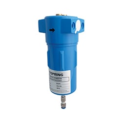
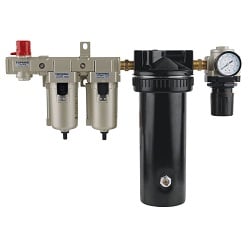
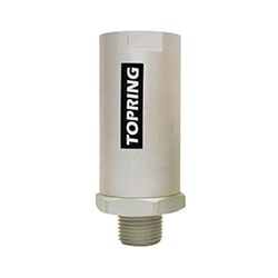
The air filter removes impurities from the airstream two ways: dynamically by centrifugal force, by which the deflector throws out heavier particles and entrained water; and statically through the filter element itself, which filters out the smaller particles. The filter provides enough filtration for most pneumatic applications; however, in situations where water and/or oil aerosols must also be filtered out, a coalescing filter should also be installed.
|
|
Number and name of the piece 1- Head 2-O-Ring 3-Bowl Ring 4-Filter Element 5-Sleeve Assembly 6-Metal Bowl 7-Bowl Baffle 8-Float Drain 9-Drain Nut 10-Drain Knob 11-Drain Clip 12-Manual Drain |
|---|

Installation
- Depressurize and lockout air pressure.
- Upstream pipes must be free of excessive dirt and liquids.
- Install the filter as close as possible to the device it is to serve.
- Install the filter so that air flows in the direction of the arrow on the filter cap.
- The filter must be installed vertically with a drain knob at the bottom.
- Filter should be installed upstream of any regulators or lubricators in the compressed air system.
Operation
- For manual drain models: Periodically drain to discharge accumulated liquids by turning the drain knob clockwise. Return to full counterclockwise position.
- For automatic drain models: Filter may be drained manually by turning the drain knob clockwise until bowl drains. Return to full counterclockwise position for automatic drain operation.
- To install 3/16 I.D. flexible tubing, push drain knob up to expose the drain clip. Remove the drain clip and drain knob. Push tubing on the stem. A tube clamp or zip tie should be used to retain tubing on drain stem.
- Replace the element when dirty. If pressure differential reaches 8 PSIG, the element MUST be replaced.
Maintenance
- Depressurize and lockout air pressure.
- Remove bowl ring and bowl assembly by turning counterclockwise.
- Remove sleeve assembly by pulling off.
- The filter element can now be removed. Elements may be cleaned by soaking several hours in soap and water, then drying them in the reverse direction to normal flow with clean, dry compressed air. However, it is strongly recommended to replace elements to ensure filter efficiency.
- To service manual or float drain, remove bowl baffle from bowl assembly. Turn drain knob counterclockwise until it stops. Then push drain knob up to expose drain clip. Remove drain clip and pull off drain knob.
- Remove drain nut by turning counterclockwise. The drain can now be removed from bowl and disassembled.
- The drain and bowl can now be cleaned.
- When re-assembling, be sure all o-rings are correctly located. Lubricate o-rings with lithium grease. Bowl baffle must be installed in correct orientation. Torque drain nut 5-15 in-lbs. Torque bowl ring hand tight.
- If the filter cannot be repaired by cleaning with soap and water, the parts should be replaced.
Bowl Drain
- Manual drains are the simplest bowl drain, but they require frequent attention to rid the bowl of accumulated water and dirt particles. If a filter is located where it is difficult to access, it might not be drained as often as it should be.
- Automatic drains are used for continuous flow applications where pressure drop might only occur at the start of the duty cycle. When liquid is present the float will rise, and the bowl will empty.
- Operating pressure: 30 PSI (minimum) and 200 PSI (maximum).
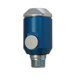
The air filter removes impurities from the airstream two ways: dynamically by centrifugal force, by which the deflector throws out heavier particles and entrained water; and statically through the filter element itself, which filters out solid particles. The filter provides enough filtration for most pneumatic applications; however, in situations where water and/or oil aerosols must also be filtered out, a coalescing filter should also be installed.
|
|
Number and name of the piece 1- Head 2-Stud 3-Upper Baffle Seal 4-O-Ring 5-Bowl Ring 6-Upper Baffle 7-Filter Element 8-Metal Bowl 9-Lower Baffle Seal 10-Lower Baffle 11-Automatic Drain 12-Drain Nut 13-Drain Knob 14-Drain Clip 15-Manual Draincock |
|---|

Installation
- Depressurize and lockout air pressure.
- Upstream pipes must be free of excessive dirt and liquids.
- Install the filter as close as possible to the device it is to serve.
- Install the filter so that air flows in the direction of the arrow on the filter cap.
- The filter must be installed vertically with a drain knob at the bottom.
- Filter should be installed upstream of any regulators or lubricators in the compressed air system.
Operation
- For manual drain models: Periodically drain to discharge accumulated liquids by turning the drain knob clockwise. Return to full counterclockwise position.
- For automatic drain models: Filter may be drained manually by turning the drain knob clockwise until bowl drains. Return to full counterclockwise position for automatic drain operation.
- To install 3/16 I.D. flexible tubing, push drain knob up to expose the drain clip. Remove the drain clip and drain knob. Push tubing on the stem. A tube clamp or zip tie should be used to retain tubing on drain stem.
- Replace the element when dirty. If pressure differential reaches 8 PSIG, the element MUST be replaced.
Maintenance
- Depressurize and lockout air pressure.
- Remove bowl ring and bowl assembly by turning counterclockwise.
- Remove lower baffle by turning counterclockwise. Then remove lower baffle seal and replace.
- The filter element can now be removed. Elements may be cleaned by soaking several hours in soap and water, then drying them in the reverse direction to normal flow with clean, dry compressed air. However, it is strongly recommended to replace elements to ensure filter efficiency.
- If needed, replace upper baffle seal. To do so, remove upper baffle. Then remove upper baffle seal and replace.
- To service automatic drain: Turn the drain knob counterclockwise until it stops, then push the drain knob up to expose the drain clip. Remove the drain clip and pull off the drain knob.
- Remove the drain nut by turning it counterclockwise. The drain can now be removed from the bowl and disassembled.
- The drain and bowl can now be cleaned.
- When re-assembling, make sure all o-rings are correctly located. Lubricate o-rings with Lithium grease. Torque drain nut 5-15 in-lbs. Torque lower baffle 50-75 in-lbs. Torque bowl ring hand tight.
- If the filter cannot be repaired by cleaning with soap and water the parts should be replaced.
Bowl Drain
- Manual drains are the simplest bowl drain, but they require frequent attention to rid the bowl of accumulated water and dirt particles. If a filter is located where it is difficult to access, it might not be drained as often as it should be.
- Automatic drains are used for continuous flow applications where pressure drop might only occur at the start of the duty cycle. When liquid is present the float will rise, and the bowl will empty.
- Operating pressure: 30 PSI (minimum) and 200 PSI (maximum).
The air filter removes impurities from the airstream two ways: dynamically by centrifugal force, by which the deflector throws out heavier particles and entrained water; and statically through the filter element itself, which filters out the smaller particles. The filter provides enough filtration for most pneumatic applications; however, in situations where water and/or oil aerosols must also be filtered out, a coalescing filter should also be installed.
|
|
Number and name of the piece 1- Head 2-Stud 3-Baffle Seals 4-O-Ring 5-Head Baffle 6-Filter Element 7-Metal Bowl 8-Lower Baffle 9-Float drain Assembly 10-Drain Nut 11-Draincock |
|---|

Installation
- Depressurize and lockout air pressure.
- Upstream pipes must be free of excessive dirt and liquids.
- Install the filter as near as possible to the device it is to serve.
- Install the filter so that air flows from inlet to outlet as shown on the head.
- The filter must be installed vertically with drain mechanism at the bottom.
- Filters should be installed upstream of any regulators or lubricators in the compressed air system.
Operation
- For manual drain models: Periodically drain to discharge accumulated liquids by turning drain cock clockwise.
- For automatic drain models, the filter may be drained manually by turning the drain stem clockwise until bowl drains. Return to the full counterclockwise position for the automatic drain position.
- To install 3/16 flexible tubing, push tubing on the stem. A tube clamp should be used to retain tubing on the drain stem.
- Replace element when dirty. If the pressure differential reaches 8 PSIG, the element MUST be replaced.
Maintenance
- Depressurize and lockout air pressure.
- Remove the bowl assembly by turning counterclockwise.
- Hold the filter element and remove lower baffle by turning wing nut counterclockwise. Then remove lower baffle and filter element.
- Elements may be cleaned by soaking several hours in soap and water, then drying them out in a reverse direction to normal flow with compressed air. However, it is strongly recommended to replace elements to ensure filter efficiency.
- To replace the filter element, make sure the filter element is oriented with the arrow toward the filter head as shown:
- Place the seals and the upper baffle as shown in the Section View.
- Place the filter element with the seals and baffle in the head. Slide the lower baffle with a new seal on the stud. Tighten the wing nut finger tight.
- To service automatic drain, remove the drain nut by turning counterclockwise. The drain can now be removed from Bowl.
- The automatic drain and bowl can now be cleaned.
- When re-assembling, be sure all o-rings are correctly located. Lubricate o-rings with Lithium grease. Torque drain nut 35-45 in-lbs. Torque bowl to head 90 to 110 ft-lbs.
- If the filter cannot be repaired by cleaning with soap and water, the parts should be replaced.
Bowl Drain
- Manual drains are the simplest bowl drain, but they require frequent attention to rid the bowl of accumulated water and dirt particles. If a filter is located where it is difficult to access, it might not be drained as often as it should be.
- Automatic drains are used for continuous flow applications where pressure drop might only occur at the start of the duty cycle. When liquid is present the float will rise, and the bowl will empty.
- Operating pressure: 30 PSI (minimum) and 200 PSI (maximum).
Pilot-operated regulators with external pilots are as precise as the pilot control regulators used. The pilot control regulator can be installed at a distance from the main regulator for convenience in adjusting. Pilot-operated regulators are of diaphragm design to provide high sensitivity and quick response.
|
|
Number and name of the piece 1- Cap Kit 2-Spring Kit 3-Valve Kit 4-Head Kit 5-Diaphragm Kit 6-Retaining Ring 7-Dome 8-Spacer |
|---|

Installation
- Depressurize and lockout air pressure.
- Upstream pipes must be free of excessive dirt and liquids. Filters should be installed immediately ahead of the regulator to insure a clean supply of air.
- Install the regulator as near as possible to the device it is to serve.
- Use the size regulator that corresponds to the maximum flow required.
- Install the regulator so that air flows in the direction indicated on the regulator.
- The regulator should be installed upstream of any lubricator in the compressed air system.
- The pilot-operated regulator has two pilot ports on front and back of inlet side of head. Connect inlet of control regulator to one of the pilot ports, and install pipe plug into the other.
- Connect outlet port of control regulator to port on bottom of pilot-operated regulator dome as shown:

- The pilot-operated regulator has two gauge ports on front and back of outlet side of head. It is necessary to install a pressure gauge or pipe plugs into each port before operating.
Operation
- The pilot-operated regulator requires a pilot control regulator to operate.
- The air pressure is regulated by force created due to the pilot pressure (supplied by control regulator) acting against the diaphragm, which opens and closes the supply valve to maintain the set pressure with flow through the regulator.
- Overpressure is relieved when pressure on the top on the diaphragm exceeds the pilot pressure acting on the bottom of the diaphragm.
Maintenance
- Depressurize and lockout air pressure.
- The supply valve can be removed by unscrewing the valve cap.
- Clean the valve seat with soap and water to remove any dirt.
- The diaphragm must be pre-loaded after assembly for proper operation. Because of this, it is not recommended that the dome be removed.
- If the regulator cannot be repaired by cleaning the valve, and the pilot control regulator is functioning properly, the regulator should be replaced.
Pilot-operated regulators with external pilots are as precise as the pilot control regulators used. The pilot control regulator can be installed at a distance from the main regulator for convenience in adjusting. Pilot-operated regulators are of diaphragm design to provide high sensitivity and quick response.
|
|
Number and name of the piece 1- Cap Kit 2-Spring Kit 3-Valve Kit 4-Head Kit 5-Diaphragm Kit 6-Retaining Ring 7-Dome 8-Spacer |
|---|

Installation
- Depressurize and lockout air pressure.
- Upstream pipes must be free of excessive dirt and liquids. Filters should be installed immediately ahead of the regulator to insure a clean supply of air.
- Install the regulator as close as possible to the device it is to serve.
- Use the size regulator that corresponds to the maximum flow required.
- Install the regulator so that air flows in the direction indicated on the regulator.
- The regulator should be installed upstream of any lubricator in the compressed air system.
- The pilot-operated regulator has two pilot ports on front and back of inlet side of head. Connect inlet of control regulator to one of the pilot ports, and install pipe plug into the other.
- Connect outlet port of control regulator to port on bottom of pilot-operated regulator dome as shown:
- The pilot-operated regulator has two gauge ports on front and back of outlet side of head. It is necessary to install a pressure gauge or pipe plugs into each port before operating.
Operation
- The pilot-operated regulator requires a pilot control regulator to operate.
- The air pressure is regulated by force created due to the pilot pressure (supplied by control regulator) acting against the diaphragm, which opens and closes the supply valve to maintain the set pressure with flow through the regulator.
- Overpressure is relieved when pressure on the top on the diaphragm exceeds the pilot pressure acting on the bottom of the diaphragm.
Maintenance
- Depressurize and lockout air pressure.
- The supply valve can be removed by unscrewing the valve cap.
- Clean the valve seat with soap and water to remove any dirt.
- The diaphragm must be pre-loaded after assembly for proper operation. Because of this, it is not recommended that the dome be removed.
- If the regulator cannot be repaired by cleaning the valve, and the pilot control regulator is functioning properly, the regulator should be replaced.
Pilot-operated regulators with external pilots are as precise as the pilot control regulators used. The pilot control regulator can be installed at a distance from the main regulator for convenience in adjusting. Pilot-operated regulators are of piston design to provide highest air flow and quick response.
|
|
Number and name of the piece 1- Cap 2-Valve Spring 3-O-Ring 4-O-Ring 5-Valve 6-Head 7-Valve Stem 8-O-Ring 9-O-Ring 10-Retaining Ring 11-O-Ring 12-O-Ring 13-Piston 14-O-Ring 15-Dome |
|---|

Installation
- Depressurize and lockout air pressure.
- Upstream pipes must be free of excessive dirt and liquids. Filters should be installed immediately ahead of the regulator to insure a clean supply of air.
- Install the regulator as close as possible to the device it is to serve.
- Use the size regulator that corresponds to the maximum flow required.
- Install the regulator so that air flows in the direction indicated on the regulator.
- The regulator should be installed upstream of any lubricator in the compressed air system.
- The pilot-operated regulator has two pilot ports on front and back of inlet side of head. Connect inlet of control regulator to one of the pilot ports, and install pipe plug into the other.
- Connect outlet port of control regulator to port on bottom of pilot-operated regulator dome as shown:
- The pilot-operated regulator has two gauge ports on front and back of outlet side of head. It is necessary to install a pressure gauge or pipe plugs into each port before operating.
Operation
- The pilot-operated regulator requires a pilot control regulator to operate.
- The air pressure is regulated by force created due to the pilot pressure (supplied by control regulator) acting against the piston, which opens and closes the supply valve to maintain the set pressure with flow through the regulator.
- Overpressure is relieved when pressure on the top on the piston exceeds the pilot pressure acting on the bottom of the piston.
Maintenance
- Depressurize and lockout air pressure.
- Remove dome by turning counterclockwise.
- Piston can now be removed.
- Remove cap by turning counterclockwise.
- Valve spring and valve can now be removed.
- When re-assembling, be sure that all seals are correctly located. Torque cap and dome to 80-100 ft-lbs.
- If the regulator cannot be repaired by cleaning with soap and water, and the pilot control regulator is functioning properly, the regulator should be replaced.
Pilot-operated regulators with external pilots are as precise as the external pilot control regulators used. The pilot control regulator can be installed at a distance from the main regulator for convenience in adjusting. Pilot-operated regulators are of piston design to provide highest air flow and quick response.
|
|
Number and name of the piece 1- Cap 2-Valve Spring 3-O-Ring 4-O-Ring 5-Poppet Valve 6-Head 7-Valve Stem 8-O-Ring 9-O-Ring 10-Retaining Ring 11-O-Ring 12-O-Ring 13-Piston 14-O-Ring 15-Dome |
|---|

Installation
- Depressurize and lockout air pressure.
- Upstream pipes must be free of excessive dirt and liquids. Filters should be installed immediately ahead of the regulator to insure a clean supply of air.
- Install the regulator as near as possible to the device it is to serve.
- Use the size regulator that corresponds to the maximum flow required.
- Install the regulator so that air flows in the direction indicated on the regulator.
- The regulator should be installed upstream of any lubricator in the compressed air system.
- The regulator comes with remote ports plugged on front and back of head. These ports MUST be plugged, do not remove.
- The pilot-operated regulator has two pilot ports on front and back of inlet side of head. Connect inlet of control regulator to one of the pilot ports, and install pipe plug into the other.
- Connect outlet port of control regulator to port on bottom of pilot-operated regulator dome as shown:

- The pilot-operated regulator has two gauge ports on front and back of outlet side of head. It is necessary to install a pressure gauge, or pipe plugs into each port before operating.
Operation
- The pilot-operated regulator requires a pilot control regulator to operate.
- The air pressure is regulated by force created due to the pilot pressure (supplied by control regulator) acting against the piston, which opens and closes the supply valve to maintain the set pressure with flow through the regulator.
- Overpressure is relieved when pressure on the top on the piston exceeds the pilot pressure acting on the bottom of the piston.
Maintenance
- Depressurize and lockout air pressure.
- Remove dome by turning counterclockwise.
- Piston can now be removed.
- Remove cap by turning counterclockwise.
- Valve spring and valve can now be removed.
- When re-assembling, be sure that all seals are correctly located. Torque cap and dome to 80-100 ft-lbs.
- If the regulator cannot be repaired by cleaning with soap and water, and the pilot control regulator is functioning properly, the regulator should be replaced.
The pressure regulator is a specialized control valve which reduces the upstream supply pressure level to a specified constant downstream pressure. Pneumatic equipment that is operated at a higher-than-recommended pressure levels wastes the energy which generates that pressure, creates a potential safety hazard and wears prematurely.
|
|
Number and name of the piece 1- Cap 2-Valve Spring 3-O-Ring 4-O-Ring 5-Valve 6-Screw 7-Valve Stem 8-Pitot Tube 9-Retainer 10-O-Ring 11-Head 12-O-Ring 13-Piston 14-O-ring 15-Spring 16-Dome 17-Adjusting Screw 18-Spring Rest 19-Nut 20-Adjusting Knob 21-Adjusting key |
|---|

Installation
- Depressurize and lockout air pressure.
- Upstream pipes must be free of excessive dirt and liquids. Filters should be installed immediately ahead of regulators to insure a clean supply of air.
- Install the regulator as close as possible to the device it is to serve.
- Install the regulator so that air flows from inlet to outlet as shown on the head.
- Regulators should be installed upstream of any lubricator or valves in the compressed air system.
- The regulator can be installed in any orientation.
- The regulator has gauge ports on both sides of the head. It is necessary to install a pressure gauge, or pipe plugs into each port before operating.
Operation
- When adjusting pressure setting, always reset from a pressure lower than the final desired setting. For example, lowering pressure from 100 psi to 50 psi should be done by decreasing pressure to 30 psi than increasing to 50 psi.
- To increase pressure, turn adjusting knob counterclockwise, to lower pressure turn clockwise.
- Pull out adjusting key for non-adjustment or remove for tamper proof.
Maintenance
- Depressurize and lockout air pressure.
- Reduce spring load to zero by turning the adjusting knob counterclockwise.
- The dome can be removed by turning it counterclockwise.
- The piston can now be removed.
- Remove cap by turning counterclockwise.
- Valve spring and valve can now be removed.
- When re-assembling, be sure all seals are correctly located. Torque cap 50-60 in-lbs. Torque Dome 200 in-lbs.
- If the regulator cannot be repaired by cleaning with soap and water, the parts should be replaced.
The pressure regulator is a specialized control valve which reduces the upstream supply pressure level to a specified constant downstream pressure. Pneumatic equipment that is operated at a higher-than-recommended pressure levels wastes the energy which generates that pressure, creates a potential safety hazard and wears prematurely.
|
|
Number and name of the piece 1- Cap 2-Valve Spring 3-O-Ring 4-O-Ring 5-Valve 6-Screw 7-Valve Stem 8-Pitot Tube 9-Retainer 10-O-Ring 11-Head 12-O-Ring 13-Piston 14-O-Ring 15-Spring 16-Dome 17-Adjusting Screw 18-Spring rest 19-Nut 20-Adjusting Knob 21-Adjusting Key |
|---|

Installation
- Depressurize and lockout air pressure.
- Upstream pipes must be free of excessive dirt and liquids. Filters should be installed immediately ahead of regulators to insure a clean supply of air.
- Filters must be installed right before the regulator to ensure clean airflow.
- Install the regulator as close as possible to the device it is to serve.
- Regulators should be installed upstream of any lubricator in the compressed air system.
- The regulator can be installed in any orientation.
- The regulator has gauge ports on both sides of the head. It is necessary to install a pressure gauge, or pipe plugs into each port before operating.
Operation
- When adjusting pressure setting, always reset from a pressure lower than the final desired setting. For example, lowering pressure from 100 psi to 50 psi should be done by decreasing pressure to 30 psi than increasing to 50 psi.
- To increase pressure, turn adjusting knob counterclockwise, to lower pressure turn clockwise.
- Pull out adjusting key for non-adjustment or remove for tamper proof.
Maintenance
- Depressurize and lockout air pressure.
- Reduce spring load to zero by turning the adjusting knob counterclockwise.
- The dome can be removed by turning it counterclockwise.
- The piston can now be removed.
- Remove cap by turning counterclockwise.
- Valve spring and valve can now be removed.
- When re-assembling, be sure all seals are correctly located. Torque cap 50-60 in-lbs. Torque Dome 200 in-lbs.
- If the regulator cannot be repaired by cleaning with soap and water, the parts should be replaced.
|
|
Number and name of the piece 1- Adjusting Knob 2-Sight Dome 3-Fill Plug 4-O-Ring 5-Cartridge assembly 6-Screw 7-Head 8-O-Ring 9-Bowl Ring 10-Feed Tube 11- Metal Bowl |
|---|

Installation
- Depressurize and lockout air pressure.
- Upstream pipes must be free of excessive dirt and liquids.
- Install the lubricator as close as possible to the device it is to serve.
- Install the lubricator so that air flows from inlet to outlet as shown on the head.
- The lubricator must be installed vertically with bowl at the bottom.
- Lubricators should be installed downstream of any filters or regulators in the compressed air system.
- Multiple lubrication points from a single lubricator is not recommended.
- The lubricator should be installed within 5 meters of the application.

Operation
- DO NOT FILL UNDER PRESSURE.
- To fill lubricator with oil, depressurize and lockout air pressure.
- Either remove fill plug or bowl assembly to add lubricant.
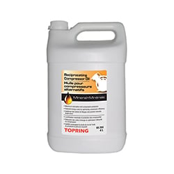
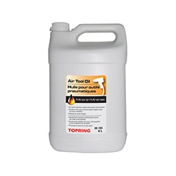
- Use the appropriate Topring Series 69 oil. Do not use compound oils containing graphite, soap fillers, etc.
- With air pressure on, the oil feed rate can be changed by turning the adjusting knob. Turn clockwise for less oil, or counterclockwise to increase oil delivery.
- The sight dome is used to monitor the oil feed rate (drops/min. etc.).
- Removal of adjusting knob will make the lubricator tamper resistant.
Maintenance
- Depressurize and lockout air pressure.
- If needed, the fill plug can be removed by turning counterclockwise and cleaned.
- Remove bowl ring and bowl assembly by turning counterclockwise.
- Both the bowl ring and bowl assembly can be cleaned.
- If needed, the cartridge assembly can be removed by unscrewing the four screws and replaced. When replacing the cartridge assembly, hand start the screw. This will ensure that the self-tapping screw use the original threads.
- When re-assembling, be sure all seals are correctly located. Torque bowl ring hand tight. Torque fill plug 10 in-lbs.
- If the lubricator cannot be repaired by cleaning with soap and water, the parts should be replaced.
|
|
Number and name of the piece 1- Adjusting Knob 2-Sight Dome 3-Fill Plug 4-O-Ring 5-Cartridge Assembly 6-Screw 7-Head 8-O-Ring 9-Bowl Ring 10-Feed Tube 11- Metal Tube |
|---|

Installation
- Depressurize and lockout air pressure.
- Upstream pipes must be free of excessive dirt and liquids.
- Install the lubricator as close as possible to the device it is to serve.
- Install the lubricator so that air flows from inlet to outlet as shown on the head.
- The lubricator must be installed vertically with bowl at the bottom.
- Lubricators should be installed downstream of any filters or regulators in the compressed air system.
- Multiple lubrication points from a single lubricator is not recommended.
- The lubricator should be installed within 5 meters of the application.

Operation
- DO NOT FILL UNDER PRESSURE.
- To fill lubricator with oil, depressurize and lockout air pressure.
- Either remove fill plug or bowl assembly to add lubricant.
- Use the appropriate Topring Series 69 oil. Do not use compound oils containing graphite, soap fillers, etc.
- With air pressure on, the oil feed rate can be changed by turning the adjusting knob. Turn clockwise for less oil, or counterclockwise to increase oil delivery.
- The sight dome is used to monitor the oil feed rate (drops/min. etc.).
- Removal of adjusting knob will make the lubricator tamper resistant.
Maintenance
- Depressurize and lockout air pressure.
- If needed, the fill plug can be removed by turning counterclockwise and cleaned.
- Remove bowl ring and bowl assembly by turning counterclockwise.
- Both the bowl ring and bowl assembly can be cleaned.
- If needed, the cartridge assembly can be removed by unscrewing the four screws and replaced. When replacing the cartridge assembly, hand start the screw. This will ensure that the self-tapping screw use the original threads.
- When re-assembling, be sure all seals are correctly located. Torque bowl ring hand tight. Torque fill plug 10 in-lbs.
- If the lubricator cannot be repaired by cleaning with soap and water, the parts should be replaced.