
Before Getting Started
- 57.500 is a single-use product.
- It should be replaced as directed to ensure its vital environmental and legally protective functions are performed correctly.
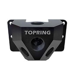
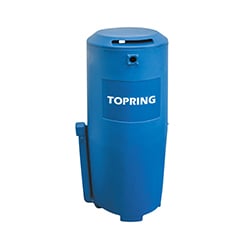
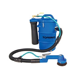
- The 57.500 water/oil separator is designed to clean condensates from a compressor operating at less than 60 CFM (1.7 m³/min) and less than 10 ppm oil-water, making it suitable for discharge into a sanitary drain.
- Make sure you have the correct fittings for your unit before installation.
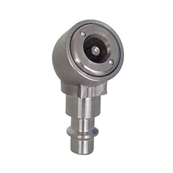
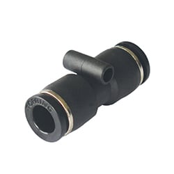
Grey ports : Compatible with imperial sizes

Black ports : Compatible with metric sizes
Installation
 |
1.Fix the wall plate vertically on a suitable wall or the compressor cabinet. Isolate the compressor and look out for cables and pipes when drilling. |
|
2. Slide the 57.500 onto the wall plate, ensuring that the vent flute is at the top.
|
|---|---|---|---|
 |
3. Connect all drain points, insert tube into push fitting in the inlet (top).
|
 |
4.Connect tube into outlet fitting and feed to drain (side). Ensure a steady fall from outlet point to drain with no kinks or tight
|

Important
Always use an automatic drain. Set timers to short open periods of one second or less. NEVER use manual drains which could flood the separator, forcing partially treated or untreated condensate to be discharged.
Maintenance
Replacement
 |
1.Ensure the condensate drain(s) are switched “OFF”. Disconnect inlet and outlet tubes from their quick fittings. |
|
2. Lift the 57.500 from the wall plate.
|
|---|---|---|---|
 |
3.Clip the retained disposal lid (that came with your kit) onto the top of the unit. |
 |
4. Insert transit plug into outlet (this comes with each kit). Please note this is designed
|
 |
5. Unit is now sealed for transport to a licensed waste disposal site. Refit the new 57.500 to the existing wall plate and connect as before. |
|

Service Indicator Assembly and Attachment
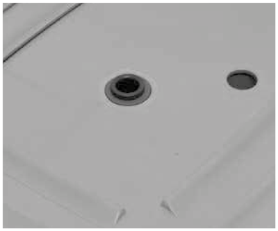
- Insert the button on the back of the bracket (c) into the pre-drilled hole of the separator cover.
- Peel off the backing of the time strip (a) and attach it to the plastic card (b) between the dotted lines.
- Bend or Flex the card, passing the ends through the slots on the upper surface of the bracket (c).
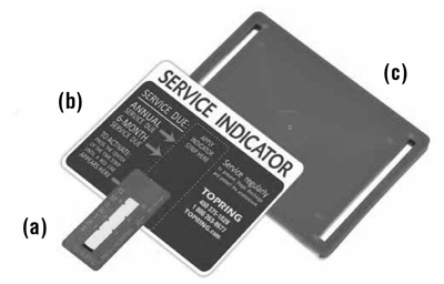
- To activate, firmly press the Timestrip label at the indicated point.
- After a few minutes, a red line will appear, indicating “service time” for up to 12 months.
- A replacement card and time strip is provided with each maintenance kit.
Installation
- Ensure a consistent downward slope in the pipe between the outlet point and the sanitary drain.
- When using a timed solenoid drain, set the drain opening duration to a minimum (1-2 seconds).
- When used with a motorized ball valve or high-capacity drain, a depressurization chamber must be installed between the drain and the TOPRING unit.
- Never discharge condensate into a stormwater system or surface water; always connect to a sanitary drain or sewer.
- Remember, it is the user’s responsibility to check with local authorities for permitted discharges in their area.
Service interval kit contains:
Fitting kit contains:
|
1. Before starting the assembly, please check the contents and ensure you have: |
|
2. Mount the inlet block on the chosen side using the provided screws. (Additional blocks can be purchased if required.)
|
|---|---|---|---|
 |
3. Insert the large blanking plug into the remaining unused port block located on the opposite side of the unit. |
 |
4. Remove the plastic bag and insert the filter bag (white netting with the top tied) by gently but firmly pushing it down to the base of the unit.
|
|
|
5. Insert the metal retainer(s) with the curved ends facing upwards. Slide it down until it touches the top of the filter bag. DO NOT compress the filter bag. |
|
6. Remove the plastic bag and insert the second filter bag (needle-felt bag with black inlet tube) and rest it on top of the retainers. |
|
|
7. Screw the inlet connector (reduction fitting) firmly into place. |
|
8. Connect the filter tube to the inlet block using the provided fittings. |
|
|
9. Attach the sampling cap to the test point. Attach your outlet hose to the fitting above. Fill the unit with water and check for leaks. |
|
10. Assemble and secure the service life indicator to the unit cover using the perforated hole. |


Maintenance
Testing quality
- Replace filters before outlet cloudiness exceeds the ppm limit for your region.
- Test outlet quality weekly using kit provided.
Service Indicator Assembly and Attachment
- Insert the button on the back of the bracket (c) into the pre-drilled hole of the separator cover.
- Peel off the backing of the time strip (a) and attach it to the plastic card (b) between the dotted lines.
- Bend or Flex the card, passing the ends through the slots on the upper surface of the bracket (c).
- To activate, firmly press the Timestrip label at the indicated point.
- After a few minutes, a red line will appear, indicating “service time” for up to 12 months.
- A replacement card and time strip is provided with each maintenance kit.
Installation
- Ensure a consistent downward slope in the pipe between the outlet point and the sanitary drain.
- When using a timed solenoid drain, set the drain opening duration to a minimum (1-2 seconds).
- When used with a motorized ball valve or high-capacity drain, a depressurization chamber must be installed between the drain and the TOPRING unit.
- Never discharge condensate into a stormwater system or surface water; always connect to a sanitary drain or sewer.
- Remember, it is the user’s responsibility to check with local authorities for permitted discharges in their area.
Service interval kit contains:
Fitting kit contains:
|
1. Before starting the assembly, please check the contents and ensure you have: |
|
2. Mount the inlet block on the chosen side using the provided screws. (Additional blocks can be purchased if necessary)
|
|---|---|---|---|
|
|
3. Insert the large blanking plug into the unused port located on the opposite side of the unit. |
|
4. Lower filter bag 1 into the separator body. Gently place it, ensuring it is in contact with the sidewall. |
|
|
5. Lower filter bag 2 into the separator body, gently placing it on top of filter bag 1. |
|
6. Install the retention springs at a 90-degree angle, directly in contact with the filter bags to prevent floating. |
|
|
7. Insert the second filter (needle-felt bag with black inlet tube) and rest it on top of the retention springs. |
|
8. Screw the inlet connector (reduction fitting) firmly into place. |
|
|
9. Connect the filter tube to the inlet block using the provided fittings. |
|
10. Attach the sampling plug to the test point. Attach your outlet hose to the fitting above. Fill the unit with water and check for leaks. |
|
|
11. Assemble and secure the service life indicator to the unit's lid using the pre-drilled hole. |
|
|


Maintenance
Testing quality
- Replace filters before outlet cloudiness exceeds the ppm limit for your region.
- Test outlet quality weekly using kit provided.
Service Indicator Assembly and Attachment
- Insert the button on the back of the bracket (c) into the pre-drilled hole of the separator cover.
- Peel off the backing of the time strip (a) and attach it to the plastic card (b) between the dotted lines.
- Bend or Flex the card, passing the ends through the slots on the upper surface of the bracket (c).
- To activate, firmly press the Timestrip label at the indicated point.
- After a few minutes, a red line will appear, indicating “service time” for up to 12 months.
- A replacement card and time strip is provided with each maintenance kit.
Installation
- Ensure a consistent downward slope in the pipe between the outlet point and the sanitary drain.
- When using a timed solenoid drain, set the drain opening duration to a minimum (1-2 seconds).
- When used with a motorized ball valve or high-capacity drain, a depressurization chamber must be installed between the drain and the TOPRING unit.
- Never discharge condensate into a stormwater system or surface water; always connect to a sanitary drain or sewer.
- Remember, it is the user’s responsibility to check with local authorities for permitted discharges in their area.
Service interval kit contains:
Fitting kit contains :
|
1. Before starting the assembly, please check the contents and ensure you have: |
|
2. Slide the connecting “yolk” over both units.
|
|---|---|---|---|
 |
3. Fit the inlet block between the separator towers using the all-thread & nut ends. Additional port blocks are available from TOPRING as an option. |
 |
4. Tighten all screws from the other side.
|
|
|
5. Insert the large blanking plug into the |
|
6. Lower the filter bag 1 into the separator body, settling it down gently, and ensuring it is in contact with the side wall. |
|
|
7. Install the securing spring clips at 90 degrees directly in contact with the filter bags to prevent floatation. (x2) |
|
8. Insert the remaining filter (the one in the needle-felt bag) with the connecting tube uppermost. (x2) |
|
|
9. Screw the inlet connector (reducing |
|
10. Connect the filter tube to the inlet block using the fittings supplied. (x2) |
|
|
11. Assemble the connecting pipes as shown below and fit onto the two units |
|
12. Attach the grab tap to the test point. Fill unit with water and check for leaks. (x2) |


Maintenance
Testing quality
- Replace filters before outlet cloudiness exceeds the ppm limit for your region.
- Test outlet quality weekly using kit provided.