
Installation
This unit has DRYSEAL pipe threads. Use pipe compound or tape sparingly to male threads only. Install unit in pipeline so air will flow in direction indicated on body. Install as close as possible to equipment serviced.

Maintenance
- To clean, it is not necessary to remove item from line.
- Refer to drawing as a guide for disassembly and reassembly.
- Depressurize air line and remove bowl.
- Blow out body with compressed air.
- Remove the auto drain assembly from the filter bowl and clean the screen.
- Disassemble the lever actuation mechanism by snapping lever out of the plastic retainer on the float and remove the pin.
- Remove the disc assembly and the float. Carefully break away the interference fit between the black plastic housing and the body and remove the piston and spring.
- Clean all component parts thoroughly with soapy water or alcohol and clean or replace all seals as necessary. Ensure that the small orifice in the housing and piston are not clogged.
- Carefully reassemble all parts positioning them as shown in drawing.
Warning
To avoid unpredictable system behaviour that can cause personal injury and property damage:
- Disconnect electrical supply (when necessary) before installation, servicing or conversion.
- Disconnect media source and depressurize all media lines connected to this product before installation, servicing, or conversion.
- Operate within the manufacturer’s specified pressure, temperature and other conditions listed in these instructions.
- Medium must be moisture-free if ambient temperature is below freezing.
- Service according to procedures listed in these instructions.
- Installation, service, and conversion of these products must be performed by knowledgeable personnel who understand how pneumatic products are to be applied.
- After installation, servicing, or conversion, media and electrical supplies (when necessary) should be connected and the product tested for proper function and leakage. If an audible leakage is present, or the product does not operate properly, do not put into use.
- Warnings and specifications on the product should not be covered by paint, etc. If masking is not possible, contact TOPRING for replacement labels.
FAILURE OR IMPROPER SELECTION OR IMPROPER USE OF THE PRODUCTS AND/OR SYSTEMS DESCRIBED HEREIN OR RELATED ITEMS CAN CAUSE DEATH, PERSONAL INJURY AND PROPERTY DAMAGE.
This web page and other information from TOPRING, and authorized distributors provide product and/or system options for further investigation by users having technical expertise. It is important that you analyze all aspects of your application, including consequences of any failure and review the information concerning the product or systems in the current product catalog.
Due to the variety of operating conditions and applications for these products or systems, the user, through its own analysis and testing, is solely responsible for making the final selection of the products and systems and assuring that all performance, safety, and warning requirements of the application are met.
The products described herein, including without limitation, product features, specifications, designs, availability and pricing, are subject to change by TOPRING and its subsidiaries at any time without notice.
Installation
-
Before connecting the drain, blow compressed air through the piping in order to thoroughly clean up any impurities within it.
-
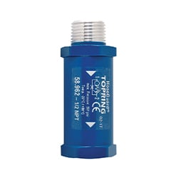
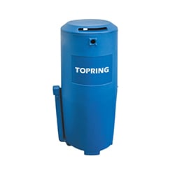
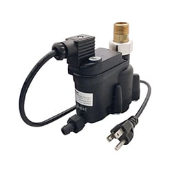
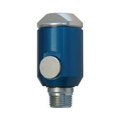
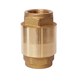
To make sure the valve is working normally, the drain should be kept in it’s vertical position, so the inlet is straight overhead (See picture).
-
Install the drain at a level below the air tank receiver, if not the air tank receiver will fill up with condensate
-
Sealing tape or sealant should be used on to the threaded part to prevent air leaks.
-
Manual drain cock (bottom) can be opened when doing maintenance to get rid of the dirt.

Precautions during installation and operation
Install the drain where pressure and temperature values do not exceed the data values
Technical Tip
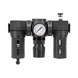
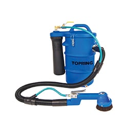
We strongly recommend that you always install a Y-strainer before the automatic air vent. By trapping muddy particles and residues, it helps prevent breakdown and extends drain service life.
Available in different diameters (59.700 / 59.702 / 59.705).

Maintenance
Weekly
Manual drain cock (bottom) can be opened when doing maintenance to get rid of the dirt. Open the manual drain cock carefully and the let water flow out and let compressed air go through a few seconds. If a significant amount of water (more than 0,5 litres) exits the valve, the drain must be thoroughly cleaned.
Annually
Dismantle the drain and clean all components. Do not use solvents to clean rubber components.
Maintenance precautions
Check that all pressurized air trapped in the system is released into the atmosphere, before each operation. When disposing of parts and waste material of any kind make sure that there is no pollution or contamination in sewer. Protect the environment by using only approved methods of disposal and consider using an oil/water separator from TOPRING.
Warning
- When handling or maintening the drain, the user must operate with care observing all instructions concerning health and safety at the installation site.
- The user should make sure that all personnel concerned with operation and maintenance of the drain have read and understood all warnings, cautions, prohibitions and notes written in this manual.
- Improper operation or maintenance of the drain could be dangerous and result in an accident causing injury or death.
- This manual cannot cover every possible hazard. If using alternative procedures, equipment, or methods not specified here, ensure they do not damage the drain, compromise safety, or pose risks to people or property.
Precautions when using compressed air
- If using compressed air for cleaning purposes, ensure safety regulations are followed and appropriate clothing and eye protection is worn.
- Never direct compressed air on to your skin or at other people.
- Never use compressed air to clean loose dirt from clothing (unless it creates a vacuum).
- Before releasing compressed air through a hose, securely hold the free end to prevent whipping, which could cause injury or equipment damage.
Component Diagram
|
Parts list
|
|

Installation
|
Each condensate source must be drained separately. |
The inlet pipe inner diameter should be 12 mm. |
If the inlet tube has an insufficient slant, use a secondary pipe for air compensation. |
|---|---|---|
|
For a proper operation the drain should be installed at a maximum slant of ± 5˚. |
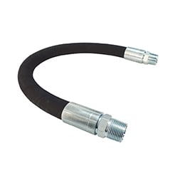
If the inlet pipe is actually a flexible hose, make sure there are no sharp bends, to |
If drainage is made on-line, pipe should be aligned in such a way as to divert air flow |


- The specific voltage of each drain is shown in the product identification label. Please make sure this value corresponds to the mains voltage before plugging it in.
- Make sure the main voltage is turned off before connecting or disconnecting the drain.
- The drain shall always be connected to the condensate collection network by means of a drain pipe.
- Never discharge directly into the environment: the fluid under pressure might damage property or cause accidents.
- Follow the local regulations enforced as to normal and special condensate disposal.
|
|
Ensure that only properly qualified skilled people have access to electrical parts. Electrical work is only allowed when the device is in a de-energized condition. Begin your installation by connecting the drain to condensate collection point and do not use the drain body as a lever. Use the required equipment on the hexagonal ring nut on inlet connection. Then connect drain to condensate stock point by using a rubber hose (12 mm I.D.) |
|---|---|

|
|
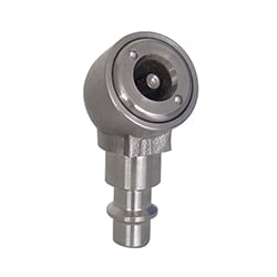
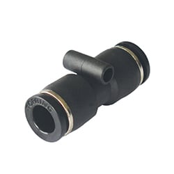
When using bottom inlet with models 59.242, 59.244, 59.246, 59.254, 59.256 or 59.258, a push-to-connect fitting (44.170 for 3/8 tubing) should be installed at top inlet for venting back to the system |
|---|---|

Operation
|
|
Stand-byThe automatic drain is connected by its inlet (1) wherever condensate needs to be drained (tank, filter, dryer, etc.). The internal tank (2) collects the liquid and the diaphragm (3) keeps the drain hole closed due to the pressure exerted on its surface. |
|---|

|
|
DrainWhen the liquid level increases, the float (4) moves up and after it reaches the highest level, the solenoid valve (5) opens the pilot valve (6). A lack of pressure on the diaphragm allows the liquid to drain to the minimum level where the pilot valve will close the drain hole without any compressed air loss. The integrated filter (7) is used to hold the impurities contained in the condensate to ensure the proper operation of the valve even in the most critical applications. The flow limiter (8) on the outlet (9) controls the drain flow by slowing it down to prevent further emulsion of the oil that in most cases is mixed with condensate. Pushing the TEST button manually opens the drain valve. |
|---|

Alarm management
(For 59.230 / 59.231 / 59.232 / 59.233 / 59.248 / 59.250 / 59.251 / 59.252 / 59.254 / 59.256 / 59.258)
The drain is equipped with a special alarm cycle that starts working in case of trouble. In the alarm state Led L2 blinks and the drain cyclically opens and closes the valve in order to drain the liquid. Simultaneously a dry contact is closed to provide a remote alarm signal. This situation persists until the drain is reset either automatically (if trouble is over) or manually (by pressing button T).
Emergencies can have a variety of causes:
- Not enough pressure in the installation
- Clogged filter
- Clogged inlet / outlet lines
- Not enough compensation in water inlet line, and more
|
|
|
|---|---|

Control panel
(For 59.230 / 59.231 / 59.232 / 59.233 / 59.248 / 59.250 / 59.251 / 59.252 / 59.254 / 59.256 / 59.258)
- The control panel on top of the drain includes a multifunction button and two state display LEDs.
- LED L1 Led indicates when it is on that the solenoid valve is energized; when it’s blinking that the valve is draining.
- LED L2 points out an alarm situation.
The multifunction button can be used in three different ways, according to situation:
- When it is pressed during normal operation it starts manual drain test.
- When it is pressed during an alarm it resets the control logic.
- By pressing it for at least 5 seconds with device on, the self-diagnosis routine will be started.
This function is very useful when the installation is over, to check if it has been successful and simulate an alarm situation without having to wait for condensate to build inside it. To return to normal operation just switch it off and on again.
| Mode | Description | L1 | L2 | Valve | Alarm |
|
Power Off
|
The drain is disconnected from the electric power line. All functions are disabled except the alarm contact that is activated. |
Off
|
Off
|
Off | On |
|
Power On
|
The drain is connected from the power line. Stand-by situation. If no water, the valve performs a short purge every 3 hours |
On
|
Off
|
1 sec. On 180 min. Off |
Off |
|
Valve draining
|
The solenoid valve opens to drain once the receiver is full. If drain is slow the valve will perform repeated opening and closing cycles |
Lampe blinking
|
Off
|
On | Off |
|
Abnormal draining
|
Slow draining or no draining. Probably caused by a clogged filter or blocked line from discharge. The valve performs an On/Off sequence to unblock the situation. |
Off
|
Lamp blinking
|
3 sec. On 60 sec. Off |
On |
|
Irreversible failure
|
Reset by holding P1 test button pressed for at least 5 seconds. Should the problem persist call technical service for action. |
Off
|
On
|
3 sec. On 60 sec. Off |
On |


NOTE : During alarm situation, the valve performs a series of short openings of 3 seconds every 60 seconds. The Off button and multifunction button begin a manual drain test
Alarm relay connection 4 pole M12 connector
|
|
Drain status | Contact status | |
| 1-2 | 3-4 | ||
| No power | Closed | Open | |
| Normal | Open | Closed | |
| Alarm | Closed | Open | |

Maintenance
Make sure the solenoid valve removes condensate regularly from collection point and periodically check the operation of the drain by pressing button (T) several times, for relatively short times, by checking the proper opening and closing of the valve. Replace the parts subject to wear once a year. Periodically clean the built-in filter, by taking it out as shown above.
Warning
During maintenance operations make sure the drain is not under pressure or alive. Use personal protection devices.
Warranty
Warranty is applicable only if a ball valve strainer is installed on the unit.
Installation
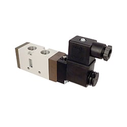
- The TOPRING Electronic Automatic Drain must be installed according to the direction of the flow, as indicated on the solenoid valve. The solenoid piping should be tilted down and equipped with an exhaust duct leading to a drain.
- In cases where it is impossible to tilt the solenoid piping down, it could be placed upward provided that:
a) a trap test port is provided to check for clogging.
b) the discharge cycle is adjusted to account for the increased volume of liquid. - Care should be taken to ensure that pipe dope, pipe tape, scale or metal chips are trapped before the solenoid valve seat. We recommend the installation of a strainer before the Electronic Automatic Drain.
Operation
The TOPRING Electronic Automatic Drain may be operated by simply connecting the provided electrical power and adjusting the desired time cycle from 1 to 60 minutes and adjusting the open drain cycle from 1 to 30 seconds.
Note : Operation of the drain should only take place when using compressed air. When the compressor is shut down the TOPRING Electronic Automatic Drain should also be disconnected. Failure to do so could lead to a solenoid burn out or premature life failure.
Manual Override
The TOPRING Electronic Automatic Drain has been equipped with a manual override switch to check drain performance or drain excessive water accumulation. This is not to be used as a massive drain for the compressed air system.
Light indicator
The switch light indicator will be "on" when the solenoid valve is in the open position during automatic or manual operation.

Maintenance
-
Your TOPRING Electronic Automatic Drain will give you years of service if the drain is properly maintained on a regular basis. It is recommended to do the maintenance monthly.
Note : Operating conditions will have to be taken into consideration and the schedule adjusted accordingly.
DO NOT APPLY ELECTRICAL POWER TO THE TOPRING ELECTRONIC AUTOMATIC DRAIN UNLESS THE UNIT IS FULLY ASSEMBLED. FAILURE TO DO SO COULD RESULT IN PERSONAL INJURY OR DAMAGE TO THE DRAIN.
- Depressurize the pneumatic system.
- Disconnect the electrical supply from the Electronic Automatic Drain.
- Remove the drain and flush the solenoid inlet and outlet ports with a safe oil cutting detergent and water.
Note: Ensure the water is kept away from all wiring and the Electronic Automatic Drain box to prevent damage to the electrical components. - Replace the drain in the system and reconnect the power. If the drain is leaking air, it may be necessary to disassemble the drain solenoid completely. Remove it from the system to clear the seat of foreign materials.
If the drain is leaking air, it may be necessary to disassemble the drain solenoid completely. Remove it from the system to clear the seat of foreign materials.
Solenoid Disassembly
Tools needed: (1) Small screwdriver / (2) Adjustable crescent wrench
- Make sure that the electrical power is disconnected.
- Remove the cover of the Electronic Automatic Drain assembly.
- Remove the nut which retains the solenoid to the coil and remove the solenoid valve. Observe the direction of flow indicated on the solenoid so that it can be reassembled in the same direction.
- Remove the stem assembly. Carefully unthread the stem assembly of the solenoid (CCW).
DO NOT STRIKE OR TWIST THE STEM WITH ANY OBJECT. DOING SO MAY DAMAGE THE ASSEMBLY. - Inspect the valve seat and remove any foreign material.
- Inspect the diaphragm or plunger assembly and remove any foreign material. If it is necessary to use a solvent, it may be used only on metal surfaces.
- Reassemble the solenoid and valve reversing the above procedures. Be sure the diaphragm and spring are aligned correctly. Be sure that the actuator cover is carefully aligned over the pin and the additional outer cast portion is positioned on the outer side of the solenoid.
- Reinstall the solenoid into the housing. Be sure the inlet and outlet are positioned correctly for the flow.
Warning
TO AVOID UNPREDICTABLE SYSTEM BEHAVIOR THAT CAN CAUSE PERSONAL INJURY AND PROPERTY DAMAGE:
- Disconnect electrical supply (when necessary) before installation,servicing, or conversion.
- Disconnect air supply and depressurize all air lines connected to this product before installation, servicing, or conversion.
- Operate within the manufacturer’s specifi ed pressure, temperature, and other conditions listed in these instructions.
- Medium must be moisture-free if ambient temperature is below freezing.
- Service according to procedures listed in these instructions.
- Installation, service, and conversion of these products must be performed by knowledgeable personnel who understand how pneumatic products are to be applied.
- After installation, servicing, or conversion, air and electrical supplies (when necessary) should be connected and the product tested for proper function and leakage. If audible leakage is present, or the product does not operate properly, do not put into use.
- Warnings and specifications on the product should not be covered by paint, etc. If masking is not possible, contact your local representative for replacement labels.
FAILURE OR IMPROPER SELECTION OR IMPROPER USE OF THE PRODUCTS AND/OR SYSTEMS DESCRIBED HEREIN OR RELATED ITEMS CAN CAUSE DEATH, PERSONAL INJURY AND PROPERTY DAMAGE.
This web page and other information from The Company, its subsidiaries and authorized distributors provide product and/or system options for further investigation by users having technical expertise. It is important that you analyze all aspects of your application, including consequences of any failure and review the information concerning the product or systems in the current product catalog. Due to the variety of operating conditions and applications for these products or systems, the user, through its own analysis and testing, is solely responsible for making the fi nal selection of the products and systems and assuring that all performance, safety and warning requirements of the application are met. The products described herein, including without limitation, product features, specifications, designs, availability and pricing, are subject to change by The Company and its subsidiaries at any time without notice.
Installation
- Verify flow direction. (stamped on valve body)
- Valve can be mounted in any position.
- Install a condensate drain on the outlet side of the drain valve for proper collection and drainage of condensate.
- If tubing is used for draining, beware of ¨WHIPPING¨ when valve is open.
- Remove Contact Block from connector and attach wires as shown at right.
Timer Settings
- Set INTERVAL time (T2) using RIGHT adjusting knob.
- Set DISCHARGE time (T1) using LEFT adjusting knob.
- Set T1 to 2 seconds and T2 to 20 minutes. (adjust as necessary)
- The Electronic Drain Valve is maintenance free. However, we recommend replacing wearing parts every TWO (2) years.
- We also recommend testing the drain every time the compressed air system is checked, by pressing the switch on the timer.
Installation
- The TOPRING Compact Programmable Digital Automatic Drain must be installed according to the direction of the flow, as indicated on the solenoid valve. The solenoid piping should be tilted down and connected to a drain.
- In cases where it is impossible to tilt the solenoid piping down, it could be placed upward provided that:
a) a trap test port is provided to check for clogging.
b) the discharge cycle is adjusted to account for the increased volume of liquid.
Operation
The TOPRING Drain may be operated by simply connecting to electrical power and adjusting the desired time cycle from 1 sec to 99h59 min 59 sec.
Note: Operation of the drain should only take place when using compressed air. When the compressor is shut down the Drain should also be disconnected. Failure to do so could lead to a solenoid burn out or premature life failure.
Manual Override
The TOPRING Electronic Automatic Drain has been equipped with a manual override switch (reset button) to check drain performance or drain excessive water accumulation.
This is not to be used as a massive drain for the compressed air system.
Mode and time settings
- When using the timer for the first time, connect to power supply. It is now in its “ON-OFF” cycle and you have to configure the timer. The “ON” mode indicates the opening of the valve and the “OFF” mode indicates the closing of the automatic drain.
- To modify the time settings, press the MODE button. Use the MODE button to choose between the “ON-OFF” or “OFF-ON” setting. Press ENTER when desired setting is displayed. As an example, if you chose the “ON-OFF” mode, at first you will choose what time the automatic drain has to be opened and then choose what time it should be closed.
- Once the setting is selected, the display will read 0:00:00. The 00.00.00 represents HOURS-MINUTES-SECONDS. Depending on the setting selected, you will set the time for “ON” or “OFF”:
- Press on the ADD button to increase the time (HH.MM.SS).
- Press ENTER on each number when desired time is shown and
- repeat for all six numbers.
- The “ON” mode is now completed and the display will show 00:00:00 for the “OFF” mode. Repeat number 3. to set the “OFF” time.
- Once complete, the display will flash 4 times and the drain will begin operating. The new settings will erase the old parameters.

Reset
To reset the timer: press the “RESET” button when it is working, the system will stop the current cycle and start the cycle from the beginning.
Maintenance
Your Drain should be properly maintained on a regular basis. It is recommended to do the maintenance monthly. The “Y” strainer needs to be emptied.
Note: Operating conditions will have to be taken into consideration and the schedule adjusted accordingly.
Warning
TO AVOID UNPREDICTABLE SYSTEM BEHAVIOR THAT CAN CAUSE PERSONAL INJURY AND PROPERTY DAMAGE:
- Disconnect electrical supply (when necessary) before installation, servicing, or conversion.
- Disconnect air supply and depressurize all air lines connected to this product before installation, servicing, or conversion.
- Operate within the specified pressure, temperature, and other conditions listed in these instructions.
- Medium must be moisture-free if ambient temperature is below freezing.
- Service according to procedures listed in these instructions.
- Installation, service, and conversion of these products must be performed by knowledgeable personnel who understand how pneumatic products are to be applied.
- After installation, servicing, or conversion, air and electrical supplies (when necessary) should be connected and the product tested for proper function and leakage. If audible leakage is present, or the product does not operate properly, do not put into use.