
Series 79 - Instruction Manual
Table of Contents
- General rules
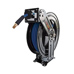
- Manual air hose reels
- Automatic closed air hose reels
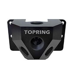
- Automatic open box-style air hose reels
- Automatic 2-arm air hose reels
- Automatic 1-arm air hose reels
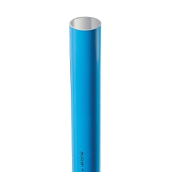
- Water hose reels
General Rules
Technical Specifications, Replacement Parts and Repair Kits
To consult the technical specifications, replacement parts list and repair kits available for your product, please visit the product page by searching for the product number (SKU) in the main menu's search bar.
Important
- The following operation, service and repair manual has been designed to give the operator/user a full understanding of the operational aspects of the hose reel.
- Topring highly recommends that any operator familiarise themselves with the following information in this manual before operating the reel to avoid injury and damage.
The Dos and Don'ts of Hose Reel Operation
- DON'T walk away from the reel pulling the hose.
- DO stand at the reel, pull out the required length of hose and block in position. Then, hold the hose close to the fitting and walk to the work area
- DON'T pull the hose from the reel by the coupler or tool.
- DO hold the hose when pulling or maneuvering the hose around.
- DON'T let the hose fly back (rewind) into the reel uncontrolled.
- DO rewind the hose back into the reel in a controlled fashion.
- DON'T allow the hose end, fitting, or tool to hit the reel.
- DO block the hose with a short section of the hose hanging from the reel with a hose bumper.
- DON'T use the hose reel if you notice the hose is cracked, split, damaged, frayed, or swelling.
- DO isolate the reel and replace the hose.
To avoid unpredictable system behavior that could result in personal injury and property damage:
- Before installing, servicing or modifying a product, shut off the compressed air supply and depressurize all components connected to the product.
- Use appropriate eye protection when assembling and using the hose reel.
- Compressed air must be free of moisture if the unit is to operate at temperatures below 0°C (32°F).
- Ensure that the hose reel is properly installed before connecting the inlet and outlet hoses.
- Follow the pressure and temperature parameters specified by the manufacturer and all conditions listed in this instruction manual.
- Maintenance must be performed in accordance with the procedures described in this instruction manual.
- Installation, maintenance and modification of a product must be performed by a person who is familiar with the handling of a pneumatic product.
- After installation, maintenance or modification of a product, the product must be tested for proper operation and leak-tightness. If there is an audible leak or the product is not working properly, do not use the product.
- Warnings and specifications on the product must not be covered by paint or any other material. If they are, contact Topring for a replacement label.
- This device may burst and cause serious injury. Never connect this device to a compressed gas cylinder.
|
|
Warning. Possible hazards, ensure you have full knowledge of the task being carried out. |
|---|---|
 |
Warning. Moving parts, keep away from moving parts and pinch points. |
 |
Warning. Part under tension, this area contains a tensioned spring. |
 |
Warning. Never let the hose rewind uncontrolled. |
 |
Consult Topring. |
Failure, improper selection or use of a product and/or items described in this instruction manual, or any related article can result in death, personal injury and property damage. This instruction manual and other information from the Company, its subsidiaries and authorized distributors provide product and/or system options that users with technical knowledge may wish to investigate further. It is important to analyze all aspects of your application, including the consequences of any failure, and to review the current product catalog for information regarding the product or systems. Because of the variety of operating conditions and applications of the products or systems, the user, through his or her own analysis and testing, is solely responsible for making the final selection of products and systems and for ensuring that all performance, safety and warning requirements of the application are met. The products described in this instruction manual, including, but not limited to, product features, specifications, designs, availability and prices, are subject to change by the Company and its subsidiaries at any time without notice.
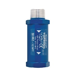
If your Hose Reel has a Hoseguard Air Fuse, please refer to the instruction manual here for additional mandatory instructions: S58-Instructions
- Unpack and inspect the reel for damage.
- Rotate the drum by hand to verify proper operation.

- Ensure that the supply line pressure does not exceed the maximum working pressure of the hose. Refer to your hose specifications for maximum working pressure on TOPRING.com .
- Depressurize and lockout air pressure.
- Lock the reel drum to prevent it from rotating.
- Install the reel on the floor, wall or ceiling, unless otherwise noted, using mounting bolts according to the number of holes available on the bracket (bolts not included).
- Exception: PolyReel reels must be installed on the floor only. They are not designed to be installed on a wall or ceiling and could cause injury or damage to equipment. The warranty may be voided if the reel is installed incorrectly.
- A flexible connection must be used between the air supply line and the reel inlet swivel joint.
- Apply sealant tape to the threads of the flexible connection and connect to the reel inlet.
- To install a main hose on the reel, apply sealant tape to the threads of the hose, connect one end to the reel outlet.
- Install hose clamps to hold the hose on the reel, if applicable.
- Wrap the entire main hose onto the reel by rotating the drum in the direction that allows the hose to be aligned with the connection on the reel without kinking.
- Apply sealant tape to the main hose outlet, then connect to an air tool.
- Check the connections for leaks.
Upkeep
- Check for leaks on a regular basis. A soapy water test is the easiest. Soapy water brushed around each joint will indicate a leak if bubbles appear.
- Inspect the hose regularly to ensure that the hose is in good working order.
- Pull the entire hose out of the reel and slide the hose between your hands to look for cuts, cracks, blisters or hardening of the outer layer of the hose. If any of these conditions are observed, replace the hose.
- Clean the hose with a cloth dampened with warm water to remove dirt and ensure proper winding.
- Do not use any fluids, detergents or solvents that may be incompatible with the materials of the hose or reel.
Hose replacement
- Depressurize and lockout air pressure before servicing the reel.
- Pull the entire hose out to expose the connection on the reel.
- Lock the reel drum to prevent it from rotating.
- Remove hose clamps, if applicable.
- Carefully disconnect the hose from the reel and remove the old hose
- Apply thread sealant to the threads of the new hose, connect one end to the outlet of the reel.
- Install hose clamps to hold it on the reel, if applicable.
- Wind all new hose onto the reel, rotating the drum in the direction that allows the hose to be aligned with the connection on the reel without kinking.
- Check connections for leaks.
- Unpack and inspect the reel for damage.
- Ensure that the supply line pressure does not exceed the maximum working pressure of the hose. Refer to your hose specifications for maximum working pressure on TOPRING.com .
- Depressurize and lockout air pressure.
- Install the reel on the wall or ceiling using mounting bolts according to the number of holes available on the bracket (bolts not included).

- The optimum height for a wall installation must allow the movement of the hose without putting intense pressure on the winding guide. This intense friction may cause, among other things, premature wear of the winding guide and/or the hose as well as inadequate rewinding.
- The optimum height for a ceiling installation is a maximum of 10 ft (3 m). When the reel is higher, it becomes difficult to correctly guide the winding of the hose, which could hinder complete winding.
- Apply sealant tape to the threads of the reel inlet hose and connect to the air supply line.
- Apply sealant tape to the outlet of the main hose, then connect to an air tool.
- Check the connections for leaks.
- To adjust the hose stop, unwind the hose from the reel and lock it at the desired length. Loosen the rubber bumper bolts and slide the bumper until it is close to the reel guide. Tighten the bolts and unlock the reel.
- The tension must be adjusted during installation to ensure the hose reel operates properly. For more information, see this video: How To Adjust the Spring Tension of A Hose Reel
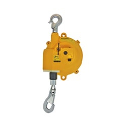
Installing the Slow-Motion Safety Mechanism
- To install the Slow-Motion Safety Mechanism (on Retracto reel models only), remove the screws holding the access plate to expose the drum gear.

- Position the Slow-Motion Mechanism by aligning its screw holes with those of the reel and secure the mechanism in place with the screws.

- As you pull the hose, you will hear a clicking noise. This is the locking pawl running over the locking teeth. When you hear this noise, stop pulling and allow the hose to retract a little. The hose will automatically lock approximately every 3 ft (1 m).
- To rewind the hose, pull it out approximately 1 ft (30 cm) and then allow it to retract while holding the hose.
- To stop rewinding and lock the hose again, pull a little bit of hose until you hear the clicking noise and allow it to retract a little, locking the hose in place.
- Never allow the hose to rewind uncontrolled. This can cause damage to property or people. Always hold the hose firmly as it retracts into the reel.
- The reel can be operated without the action of the locking pawl: the hose is then constantly pulled towards the reel without the lock blocking the hose. Open the plate on the hose side to access the mechanism and change the position of the pawl spring from “On” by unhooking it and re-hooking it on the opposite side to “Off”.

Upkeep
- Check for leaks on a regular basis. A soapy water test is the easiest. Soapy water brushed around each joint will indicate a leak if bubbles appear.
- Inspect the hose regularly to ensure that the hose is in good working order.
- Pull the entire hose out of the reel and slide the hose between your hands to look for cuts, cracks, blisters or hardening of the outer layer of the hose. If any of these conditions are observed, replace the hose.
- Clean the hose with a cloth dampened with warm water to remove dirt and ensure proper winding.
- Do not use any fluids, detergents or solvents that may be incompatible with the materials of the hose or reel.
- This reel contains a spring under tension that can cause injury or damage to equipment and may void the warranty if the reel is opened improperly. For any interior repairs, contact Topring.
- Unpack and inspect the reel for damage.
- Ensure that the supply line pressure does not exceed the maximum working pressure of the hose. Refer to your hose specifications for maximum working pressure on TOPRING.com .
- Depressurize and lockout air pressure.
- Install the reel on the floor or wall using mounting bolts according to the number of holes available on the bracket (bolts not included).

- The optimum height for a wall installation must allow the movement of the hose without putting intense pressure on the winding guide. This intense friction may cause, among other things, premature wear of the winding guide and/or the hose as well as inadequate rewinding.
- The optimum height for a ceiling installation is a maximum of 10 ft (3 m). When the reel is higher, it becomes difficult to correctly guide the winding of the hose, which could hinder complete winding.
- A flexible connection must be used between the air supply line and the reel inlet swivel joint.
- Apply sealant tape to the threads of the flexible connection and connect the reel inlet and to the air supply line.
- Apply sealant tape to the outlet of the main hose, then connect to an air tool.
- Check the connections for leaks.
- To adjust the hose stop, unwind the hose from the reel and lock it at the desired length. Loosen the rubber bumper bolts and slide the bumper until it is close to the reel guide. Tighten the bolts and unlock the reel.
- The tension must be adjusted during installation to ensure the hose reel operates properly. For more information, see this video: How To Adjust the Spring tension of A Hose Reel
- As you pull the hose, you will hear a clicking noise. This is the locking pawl running over the locking teeth. When you hear this noise, stop pulling and allow the hose to retract a little. The hose will automatically lock approximately every 3 ft (1 m).
- To rewind the hose, pull it out approximately 1 ft (30 cm) and then allow it to retract while holding the hose.
- To stop rewinding and lock the hose again, pull a little bit of hose until you hear the clicking noise and allow it to retract a little, locking the hose in place.
- Never allow the hose to rewind uncontrolled. This can cause damage to property or people. Always hold the hose firmly as it retracts into the reel.
Upkeep
- Check for leaks on a regular basis. A soapy water test is the easiest. Soapy water brushed around each joint will indicate a leak if bubbles appear.
- Inspect the hose regularly to ensure that the hose is in good working order.
- Pull the entire hose out of the reel and slide the hose between your hands to look for cuts, cracks, blisters or hardening of the outer layer of the hose. If any of these conditions are observed, replace the hose.
- Clean the hose with a cloth dampened with warm water to remove dirt and ensure proper winding.
- Do not use any fluids, detergents or solvents that may be incompatible with the materials of the hose or reel.
- This reel contains a spring under tension that can cause injury or damage to equipment and may void the warranty if the reel is opened improperly. For any interior repairs, contact Topring.
Hose Replacement
- Depressurize and lockout air pressure before servicing the reel.
- Pull the entire hose out to expose the connection on the reel.
- Lock the reel drum to prevent it from rotating.
- Remove hose clamps, if applicable.
- Carefully disconnect the hose from the reel and remove the old hose
- Apply thread sealant to the threads of the new hose, connect one end to the outlet of the reel.
- Install hose clamps to hold it on the reel, if applicable.
- Wind all new hose onto the reel, rotating the drum in the direction that allows the hose to be aligned with the connection on the reel without kinking.
- Check connections for leaks.
Adjusting Spring Tension
If necessary, adjust the spring tension of the winding mechanism by adding or removing turns of hose, one turn at a time, until the desired tension is reached.
Add turns to increase tension. Remove turns to decrease tension.
Visit TOPRING.com to see the procedure for adjusting spring tension.
Use extreme caution, mechanism under tension. Unsafe practices can result in personal injury or damage to the unit. Always disconnect and lock out the compressed air system before servicing. Avoid disengaging the locking mechanism.
To Increase Tension
- Pull the hose out, leaving approximately 15 ft (4.6 m) in the reel. Make sure the locking mechanism is engaged.
- Lock the reel drum to prevent it from rotating.
- Carefully remove the rubber bumper without activating the rewind.
- Manually wrap the hose around the spool, making it shorter.
- When adding turns of hose, do only one (1) turn at a time to avoid exceeding the spring capacity on the mechanism. Damage to the winding mechanism may occur if the spring is over-tensioned.
- Return the bumper to the desired position.
To Decrease Tension
- Pull the hose 5 ft (1.5 m) out of the reel. Ensure the locking mechanism is engaged.
- Lock the reel drum to prevent it from rotating.
- Carefully remove the rubber bumper without activating the rewind.
- Manually unwind turns of hose from around the reel, making it looser.
- Return the bumper to the desired position.
- Unpack and inspect the reel for damage.
- Ensure that the supply line pressure does not exceed the maximum working pressure of the hose. Refer to your hose specifications for maximum working pressure on TOPRING.com .
- Depressurize and lockout air pressure.
- The reel has adjustable guide arms and winding guide. Depending on where the reel is placed, it may be necessary to adjust the guide arm and/or winding guide. If adjustment is necessary:
- Unwind approximately 5 ft (1.5 m) of hose and engage the locking mechanism.
- Remove the bolts from each guide arm and pivot to the appropriate position.
- Remove the bolts from the winding guide and pivot to the appropriate position.
- Replace the bolts and return the hose to the inside of the reel.
- Install the reel on the floor, wall or ceiling using mounting bolts according to the number of holes available on the bracket (bolts not included).

- The optimum height for a wall installation must allow the movement of the hose without putting intense pressure on the winding guide. This intense friction may cause, among other things, premature wear of the winding guide and/or the hose as well as inadequate rewinding.
- The optimum height for ceiling installation is a maximum of 15 ft (4.6 m). When the reel is higher, it becomes difficult to guide the hose winding properly, which could hinder complete winding.
- A flexible connection must be used between the air supply line and the reel inlet swivel joint.
- Apply sealant tape to the threads of the flexible connection and connect to the reel inlet.
- Apply sealant tape to the outlet of the reel main hose, then connect to an air tool.
- Check the connections for leaks.
- To adjust the hose stop, unwind the hose from the reel and lock it at the desired length. Loosen the rubber bumper bolts and slide the bumper until it is close to the reel guide. Tighten the bolts and unlock the reel.
- The tension must be adjusted during installation to ensure the hose reel operates properly. For more information, see this video: How To Adjust the Spring tension of A Hose Reel
- As you pull the hose, you will hear a clicking noise. This is the locking pawl running over the locking teeth. When you hear this noise, stop pulling and allow the hose to retract a little. The hose will automatically lock approximately every 3 ft (1 m).
- To rewind the hose, pull it out approximately 1 ft (30 cm) and then allow it to retract while holding the hose.
- To stop rewinding and lock the hose again, pull a little bit of hose until you hear the clicking noise and allow it to retract a little, locking the hose in place.
- Never allow the hose to rewind uncontrolled. This can cause damage to property or people. Always hold the hose firmly as it retracts into the reel.
Upkeep
- Check for leaks on a regular basis. A soapy water test is the easiest. Soapy water brushed around each joint will indicate a leak if bubbles appear.
- Inspect the hose regularly to ensure that the hose is in good working order.
- Pull the entire hose out of the reel and slide the hose between your hands to look for cuts, cracks, blisters or hardening of the outer layer of the hose. If any of these conditions are observed, replace the hose.
- Clean the hose with a cloth dampened with warm water to remove dirt and ensure proper winding.
- Do not use any fluids, detergents or solvents that may be incompatible with the materials of the hose or reel.
- This reel contains a spring under tension that can cause injury or damage to equipment and may void the warranty if the reel is opened improperly. For any interior repairs, contact Topring.
Hose replacement
- Depressurize and lockout air pressure before servicing the reel.
- Pull the entire hose out to expose the connection on the reel.
- Lock the reel drum to prevent it from rotating.
- Remove hose clamps, if applicable.
- Carefully disconnect the hose from the reel and remove the old hose
- Apply thread sealant to the threads of the new hose, connect one end to the outlet of the reel.
- Install hose clamps to hold it on the reel, if applicable.
- Wind all new hose onto the reel, rotating the drum in the direction that allows the hose to be aligned with the connection on the reel without kinking.
- Check connections for leaks.
Adjusting Spring Tension
If necessary, adjust the spring tension of the winding mechanism by adding or removing turns of hose, one turn at a time, until the desired tension is reached.
Add turns to increase tension. Remove turns to decrease tension.
Visit TOPRING.com to see the procedure for adjusting spring tension.
Use extreme caution, mechanism under tension. Unsafe practices can result in personal injury or damage to the unit. Always disconnect and lock out the compressed air system before servicing. Avoid disengaging the locking mechanism.
To Increase Tension
- Pull the hose out, leaving approximately 15 ft (4.6 m) in the reel. Make sure the locking mechanism is engaged.
- Lock the reel drum to prevent it from rotating.
- Carefully remove the rubber bumper without activating the rewind.
- Manually wrap the hose around the spool, making it shorter.
- When adding turns of hose, do only one (1) turn at a time to avoid exceeding the spring capacity on the mechanism. Damage to the winding mechanism may occur if the spring is over-tensioned.
- Return the bumper to the desired position.
To Decrease Tension
- Pull the hose 5 ft (1.5 m) out of the reel. Ensure the locking mechanism is engaged.
- Lock the reel drum to prevent it from rotating.
- Carefully remove the rubber bumper without activating the rewind.
- Manually unwind turns of hose from around the reel, making it looser.
- Return the bumper to the desired position.
- Unpack and inspect the reel for damage.
- Ensure that the supply line pressure does not exceed the maximum working pressure of the hose. Refer to your hose specifications for maximum working pressure on TOPRING.com .
- Depressurize and lockout air pressure.
- The reel has an adjustable guide arm. Depending on where the reel is placed, it may be necessary to adjust the guide arm. If adjustment is necessary:
- Unwind approximately 5 ft (1.5 m) of hose and engage the locking mechanism.
- Remove the bolts from the guide arm and pivot to the appropriate position.
- Replace the bolts and return the hose to the inside of the reel.
- Install the reel on the floor, wall or ceiling using mounting bolts according to the number of holes available on the bracket (bolts not included).
- The optimum height for a wall installation must allow the movement of the hose without putting intense pressure on the winding guide. This intense friction may cause, among other things, premature wear of the winding guide and/or the hose as well as inadequate rewinding.
- The optimum height for ceiling installation is a maximum of 15 ft (4.6 m). When the reel is higher, it becomes difficult to guide the hose winding properly, which could hinder complete winding.
- A flexible connection must be used between the air supply line and the reel inlet swivel joint.
- Apply sealant tape to the threads of the flexible connection and connect to the reel inlet.
- Apply sealant tape to the outlet of the main hose, then connect to an air tool.
- Check the connections for leaks.
- To adjust the hose stop, unwind the hose from the reel and lock it at the desired length. Loosen the rubber bumper bolts and slide the bumper until it is close to the reel guide. Tighten the bolts and unlock the reel.
- The tension must be adjusted during installation to ensure the hose reel operates properly. For more information, see this video: How To Adjust the Spring tension of A Hose Reel
- As you pull the hose, you will hear a clicking noise. This is the locking pawl running over the locking teeth. When you hear this noise, stop pulling and allow the hose to retract a little. The hose will automatically lock approximately every 3 ft (1 m).
- To rewind the hose, pull it out approximately 1 ft (30 cm) and then allow it to retract while holding the hose.
- To stop rewinding and lock the hose again, pull a little bit of hose until you hear the clicking noise and allow it to retract a little, locking the hose in place.
- Never allow the hose to rewind uncontrolled. This can cause damage to property or people. Always hold the hose firmly as it retracts into the reel.
Upkeep
- Check for leaks on a regular basis. A soapy water test is the easiest. Soapy water brushed around each joint will indicate a leak if bubbles appear.
- Inspect the hose regularly to ensure that the hose is in good working order.
- Pull the entire hose out of the reel and slide the hose between your hands to look for cuts, cracks, blisters or hardening of the outer layer of the hose. If any of these conditions are observed, replace the hose.
- Clean the hose with a cloth dampened with warm water to remove dirt and ensure proper winding.
- Do not use any fluids, detergents or solvents that may be incompatible with the materials of the hose or reel.
- This reel contains a spring under tension that can cause injury or damage to equipment and may void the warranty if the reel is opened improperly. For any interior repairs, contact Topring.
Hose Replacement
- Depressurize and lockout air pressure before servicing the reel.
- Pull the entire hose out to expose the connection on the reel.
- Lock the reel drum to prevent it from rotating.
- Remove hose clamps, if applicable.
- Carefully disconnect the hose from the reel and remove the old hose
- Apply thread sealant to the threads of the new hose, connect one end to the outlet of the reel.
- Install hose clamps to hold it on the reel, if applicable.
- Wind all new hose onto the reel, rotating the drum in the direction that allows the hose to be aligned with the connection on the reel without kinking.
- Check connections for leaks.
Adjusting Spring Tension
If necessary, adjust the spring tension of the winding mechanism by adding or removing turns of hose, one turn at a time, until the desired tension is reached.
Add turns to increase tension. Remove turns to decrease tension.
Visit TOPRING.com to see the procedure for adjusting spring tension.
Use extreme caution, mechanism under tension. Unsafe practices can result in personal injury or damage to the unit. Always disconnect and lock out the compressed air system before servicing. Avoid disengaging the locking mechanism.
To Increase Tension
- Pull the hose out, leaving approximately 15 ft (4.6 m) in the reel. Make sure the locking mechanism is engaged.
- Lock the reel drum to prevent it from rotating.
- Manually wrap the hose around the spool, making it shorter.
- When adding turns of hose, do only one (1) turn at a time to avoid exceeding the spring capacity on the mechanism. Damage to the winding mechanism may occur if the spring is over-tensioned.
To Decrease Tension
- Pull the hose 5 ft (1.5 m) out of the reel. Ensure the locking mechanism is engaged.
- Lock the reel drum to prevent it from rotating.
- Manually unwind turns of hose from around the reel, making it looser.
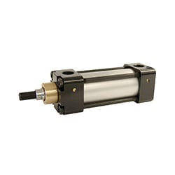
 Figure 1. General dimensions
Installing the reel
The hose reel is fitted with an all-position latch system which allows the reel to operate in all positions.
The reel is supplied with swivel mounting brackets for ceiling or wall installation. A fixed mounting bracket (item 79.142) is available as an option for a fixed installation that does not require the reel to swivel.
The optimum height for wall installation should allow the hose to be pulled at an angle of no more than ≈ 15°. An angle exceeding this risks creating excessive friction and potentially causing premature wear to the hose guide bracket of the reel.
The optimum height for ceiling installation is a maximum of 15 feet (4.6 m). When the reel is higher, it becomes difficult to guide the hose reel correctly, which could hinder complete rewinding.
Always support the weight of the reel during its installation in the mounting bracket.
The orientation of the swivel mounting brackets is important, follow the illustrations carefully.

Figure 2. Installation options.
When installing the reel, DO NOT leave the reel hanging unsupported in one (1) mounting bracket. Leaving the reel hanging from a single bracket places unnecessary pressure on the lower knob and may cause the knob to fail immediately. If it does not break immediately, the knob can be severely weakened and fail later during normal use (Figure 3).

Figure 3. Pommel breakage.
Connecting the air supply hose
A flexible inlet connection between the hose reel and the air supply is necessary to prevent possible misalignment and jamming. A non-flexible connection will void the warranty.
The pressure rating of the inlet hose must be equal to or greater than the rating of the main hose.
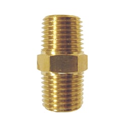
Use appropriate hose fittings to connect the supply line to the inlet connection of the reel.
Use thread sealants where appropriate. Never over-tighten or under-tighten fittings.
Once the connection has been made to the inlet of the reel, turn the supply valve on slowly and check for leaks.

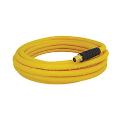
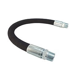
Figure 4. Air supply hose.
When pulling out the hose, you will hear a clicking noise. This is the locking pawl running over the ratchet teeth. When this noise is heard, stop pulling, and allow the hose to retract a little. The hose will lock at approximately every 3 ft (1 m).
To rewind the hose, pull it out about 1 ft (30 cm), then let it retract while holding the hose. To stop rewinding and re-lock it in position again, pull some hose out until you hear it click and let it retract a little, locking the hose in position.
Never let the hose rewind back uncontrolled. This can cause damage to property or persons. Always keep a firm hold of the hose as it is retracting back into the reel.
Locking the reel
We recommend inserting a locking pin through the outer casing to prevent the drum from being able to rotate during maintenance work or when the reel is being transported.
- Rotate the drum by pulling the hose slowly and look into one service pin hole (one on each side, Figure 5).
- When the pin holes line up, insert the pin right through the reel so that it protrudes out the opposite side. Secure the pin to prevent movement.

Figure 5. Pin lock.
Leak detection
We recommend checking for leaks on a regular basis. Soapy water is the simplest test. Soapy water brushed around each joint will indicate a leak if/when bubbles appear.
Checking for hose damage
Pull the entire hose from the reel and lock it in the final position. Slide the hose between your hands, and check for cuts, cracks, blistering or hardening of the hose’s outer layer. Should you find any of these conditions, replace the hose.
Replacing the swivel
- Pull the hose all the way out of the reel and use a locking pin to lock the reel (see Locking the reel section).
- Disconnect the inlet air supply from the reel and depressurize the hose.
- Remove the six (6) screws of the inlet side plate.
- Remove the inlet side plate and pull out the swivel.
- The hose is connected to the inner drum with a cable tie. Cut the cable tie being careful not to cut the hose.
- Pull the hose out far enough to allow free access to the swivel.
- Disconnect the swivel from the hose.
- Reconnect the main hose to the new swivel.
- Replace the new swivel in position.
- Replace the cable tie to secure the hose to the inner drum.
- Replace the inlet side plate and the six (6) screws.
- Reconnect the inlet air supply and check for leaks (see Leak Detection section).
- Remove the locking pin while holding the hose and allow the hose to retract.
Never open the tension side plate with the hose fully or partially extended from the reel. All of the hose must be fully wound onto the reel.

Figure 6. Accessing the pivot.
Increasing the tension
Never adjust the tension with the hose fully or partially extended. All of the hose must be fully wound onto the reel.
- With the hose fully recoiled in the reel, remove the two (2) inner screws of the centre tension cap on the tension side plate (Figure 7).
- Using the tension adjustment tool, (optional, 79.144), rotate the cap clockwise one (1) full turn (The tensioning cap is a ratchet system, a clicking sound will be heard when turning the cap).
- Only add one (1) full turn at a time. NEVER add more than three (3) turns.
- Before replacing the screws, pull on the hose to ensure that all the hose comes out.
- If it is not possible to unwind the hose completely with no hose remaining in the reel, the spring is over-tensioned. In this case, remove the excess tension (see Decreasing Tension section).
- When tension is satisfactory, replace the two (2) screws to lock the cap in position.

Figure 7. Increase tension.
Decreasing the tension
Never adjust the tension with the hose fully or partially extended. All of the hose must be fully wound onto the reel before beginning.
- With the hose fully wound in the reel, use the tension adjustment tool, (optional, 79.144), to hold the central tension cap, and remove the four (4) screws (Figure 8).
There is tension on this cap and it will want to turn anti-clockwise. Hold tightly.
- Once the screws have been removed, allow the cap to unwind in a controlled manner.
- When all the tension is released, the cap will remain stationary.
- Replace the four (4) screws making sure to align the cap and the tension side plate.

Figure 8. To remove tension
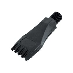
Replacing the hose guide bracket
The amount of wear on the hose guide bracket depends on the use frequency.- Pull a small amount of hose from the reel and latch it in position.
- Remove the 4 screws as shown below.
- Slightly separate the housings to pop the hose guide bracket out.
- Remove the hose bumper and slide the hose guide bracket off.
- Fit the new hose guide bracket in reverse order to the previous steps.

Figure 9. Access to pipe alignment support.
Replacing the hose
Ensure the replacement hose is the same length and diameter as the hose originally supplied on the reel. Longer lengths or larger diameters will damage the reel and void the warranty.
Pull the hose all the way out of the reel and use a locking pin to lock the reel (see Locking the Reel section).
- Disconnect the inlet air supply from the reel and depressurize the hose.
- Remove the six (6) screws of the inlet side plate.
- Remove the inlet side plate and pull out the swivel.
- The hose is connected to the inner drum with a cable tie. Cut the cable tie being careful not to cut the hose.
- Full the hose out far enough to get free access to the swivel.
- Disconnect the swivel from the hose.
- Feed the replacement hose through the hose guide bracket of the reel and then through the opening in the drum.
- Connect the replacement hose to the swivel.
- Fit the swivel in position.
- Replace the cable tie to hold the hose to the inner drum.
- Replace the inlet side plate and the six (6) screws.
- Reconnect the inlet air supply and check for leaks (see Leak Detection section).
- Remove the locking pin while holding the hose and allow the hose to retract.
Never open the tension side plate with the hose fully or partially extended from the reel. All of the hose must be fully wound onto the reel.
Figure 10. Pivot access.
Replacing the latch system
Never open the tension side plate with the hose fully or partially extended. The entire hose must be fully wound onto the reel.
- With the hose fully wound in the reel, use the tension adjustment tool, (optional, 79.144) to hold the central tension cap, and remove the four (4) screws.
There is tension on this cap and it will want to spin anti-clockwise. Hold tightly.
- Once the screws have been removed, allow the cap to unwind in a controlled manner.
- When all the tension is released, the cap will remain stationary.
- Remove the six (6) screws holding the side tension plate and the one (1) screw located in the centre of the tension cap.
- Remove the tension side plate.
- Inspect the ratchet teeth located on the inner drum for damage. If the ratchet teeth are damaged or broken, replace the spring drum canister (see Replacing the spring drum section).
- Install the new tension side plate assembly and the six (6) screws.
- Replace the central tension cap and the one (1)+ four (4) screws.
- Re-tension the reel (see Adding tension section).

Figure 11. Access to locking mechanism.
Replacing the spring drum
Never open the tension side plate with the hose fully or partially extended. The entire hose must be fully wound onto the reel.
Never open the spring drum assembly as it contains a coiled spring and could cause serious injury.
- Disconnect the inlet air supply from the reel and depressurize the hose.
- With the hose fully wound in the reel, use the tension adjustment, (optional, 79.144) tool to hold the central tension cap, and remove its 4 screws.
There is tension on this cap and it will want to spin anti-clockwise. Hold tightly.
- Once the screws have been removed, allow the cap to unwind in a controlled manner.
- When all the tension has been released, the cap will remain stationary.
- Remove the six (6) screws holding the tension side plate and the one (1) screw located in the centre of the tension wheel.
- Remove the tension side plate.
- Remove the six (6) screws holding the inlet side plate.
- Remove the inlet side plate and pull out the swivel.
- The hose is connected to the inner drum with a cable tie. Cut the cable tie being careful not to cut the hose.
- Pull the hose out sufficiently to allow free access to the swivel.
- Disconnect the swivel from the hose.
- Remove the screws around the outer case and split the two (2) halves.
- Install the new spring drum into the case halves and replace the outer case screws.
- Feed the hose through the hose guide bracket of the reel and then through the opening in the drum.
- Reconnect the main hose to the swivel.
- Fit the swivel in position.
- Replace the cable tie to secure the hose to the inner drum.
- Replace the inlet side plate and the six (6) screws.
- Reconnect the inlet air supply and check for leaks (see Leak Detection section).
- Replace the tension side plate and the six (6) screws.
- Replace the central tension cap and the one (1)+ four (4) screws.
- Re-tension the reel (see Adding tension section).
Replacing the spring drum (continued)

Figure 12. Access to spring drum.
Not all items are sold as individual parts; complex assemblies and spring assemblies are sold in sub-assembly kits (Figure 13).
Use only original Topring components; failure to do so will void the warranty.
|
Parts list 1. Outer case (pair) 2. Swivel mounting brackets (pair) 3. Nylon hose guide bracket 4. Cable tie 5. Screw #8 x 3/4” 6. Hose bumper 7. Hose ferrule 8. Hose barb 1/2” x 1/2” NPT 9. Bolt 1/4” x 1-1/4” and nut 1/4” |
Figure 13. Overview
|

Inlet side plate and Swivel assembly
|
Parts list 10. Outer case (pair) 11. Swivel hose barb 1/2” x 1/2” NPT 12. Swivel body 1/2” NPT 13. Swivel shaft 1/2” NPT 14. O-ring NBR 15. External circlip 22mm |
Figure 14. Exploded view of air inlet side plate and pivot. |

Tension side plate assembly
|
Parts list 5. Screw #8 x 3/4” 32. Torsion spring locking pawl 34. Push-on fastener 12mm 37. Pawl 38. Push-on fastener M4 39. Tension side plate 40. Tension cap 41. Ratchet locking ring
|
Figure 15. Exploded view of tension side plate |

Spring drum assembly
|
Parts list 31. Main spring 33. Inner drum (pair) 35. Bolt M5 x 60mm 36. Drum axle
|
Figure 16. Exploded view of the spring drum.
|

IMPROTANT
Read this manual carefully before installing, operating or servicing this equipment.
WARNING
Read this manual carefully before installing, operating or servicing this equipment.
SAFETY PRECAUTIONS
Personal injury and/or equipment damage may result if proper safety precautions are not observed.
• Ensure that only a qualified electrician installs/services this equipment.
• Ensure that power supply voltage does not exceed maximum voltage rating of reel.
• Ensure that reel is properly installed before connecting to power supply.
• All cord reels with flying leads must be hard wired to ensure proper function.
• Ensure that all electrical power is removed from reel before servicing.
• A high-tension spring assembly is contained within the reel. Exercise extreme caution.
• Check for frayed and/or broken wires before each use. Pull electrical cord from reel by grasping the electrical cord itself, not the work device.
• If an electrical malfunction should occur, remove power from reel immediately.
• Ensure that reel, electrical cord, and equipment being serviced are properly grounded. Use an ohmmeter to check ground continuity.
• If reel ceases to unwind or rewind, remove power immediately. Do not pull or jerk on electrical cord!
• Treat and respect the reel as any other piece of machinery, observing all common safety practices.

MOUNTING CAUTION:
Unless reel was specified differently when ordering, maximum installation height is 16 feet. Do not exceed this distance.
Ensure that only a qualified electrician installs/services this equipment. Installation of cord reels should be performed by a qualified and licensed professional in accordance with building codes and applicable NEC standards.
1. Unpack and inspect reel for damage. Turn by hand to check for smooth operation. Check for completeness.
2. Configure reel for top, side or bottom wind (bottom-wind for constant tension reels only) electrical cord dispensing by removing bolts (1), securing guide arm bracket (2). Determine new guide arm location and remove corresponding bolts. Position guide arm bracket to reel and replace bolts.
3. Position reel on floor, wall, or ceiling. Secure into place, using four (customer supplied) screws or bolts (3).
INSTALLING THE INPUT ELECTRICAL CABLE

WARNING :
Use only cable 12/3 or 16/3 for input wiring. Ensure that application does not exceed electrical rating of
reel.
Secure into place, using four (customer supplied) screws or bolts (3).
1. Feed input cable (1) through main shaft. Make sure that input cable extends 6” from collector.
2. Screw elbow (3) into reel.
3. Connect input wires (1) and collector ring wires (10) together using splicing connectors (11).
4. Take the provided zip tie (not pictured) and zip tie the input cable wires together closest to the slip ring.
INSTALLING THE OUTPUT ELECTRICAL CABLE

WARNING:
Select output cable in accordance with power requirement of apparatus to be supplied. Ensure that application does not exceed electrical rating of reel.
Use extreme caution, reel under tension. Avoid releasing latch mechanism.
1. Manually turn sheave (7) until spring is tight, back off 2 turns, and latch.
2. Remove access cover (8).
3. Remove 6” of output cable outer jacket (1).
4. Route cable through strain relief (3), then through cut out in spool (4).
5. Pull the route cable through for the sheave (7), then connect splicing connectors to the (13).
6. Connect input wires (3) to the sheave (7) as shown.
7. Using Ohmmeter check for ground faults.
8. Replace cover (8).
9. Release latch and wind cable onto reel.
10. Install bumper stop (2).
ADJUSTMENTS- SPRING TENSION
If necessary, adjust spring tension on reel by adding or removing wraps of electrical cord from spool, one wrap at a time, until desired tension is obtained. Add wraps to increase tension. Remove wraps to decrease tension.
WARNING: When adding wraps of electrical cord, be careful not to exceed the winding mechanism’s spring capacity. Add just enough wraps of cord to achieve the desired tension. Damage to the winding mechanism will result if spring is over-tensioned. Always be aware of spring tension on reel. Exercise extreme caution.
TROUBLESHOOTING INSTRUCTIONS
If necessary, adjust spring tension on reel by adding or removing wraps of electrical cord from spool, one wrap at a time, until desired tension is obtained. Add wraps to increase tension. Remove wraps to decrease tension.
WARNING:
The following procedure directs the technician to take voltage measurements. Remember, even low voltage is dangerous and can cause personal injury or death. Exercise extreme caution! Ensure that only a qualified electrician installs/services this equipment.
1. If work device is either an incandescent, replace bulb with a known good bulb. If this does not correct the problem, proceed to step (2.) If work device is an electrical receptacle, ensure that tool or fixture connected to it is in good working order. If it is, proceed to step (2).
2. Remove power from reel.
3. Remove access cover (8).
4. Reapply power to reel.
5. Check for correct voltage (120 V AC) at splicing connectors (11). If voltage reading is correct, replace output electrical cord/work device (refer to Service Instructions). If voltage reading is incorrect, proceed to step 6.
6. Disconnect power from reel.
7. Using ohmmeter, check continuity of input electrical cord. If cord checks good, proceed to step 8.If cord is faulty, replace it (refer to Service Instructions).
8. Remove brushes (12) from reel and inspect (refer to Service Instructions). Replace defective components then proceed to step 9.
9. Reapply power to reel.
10. Check for correct voltage (120 V AC) at splicing connectors (11). If voltage reading is still incorrect, replace defective collector assembly (11) (refer to Service Instructions).
11. Replace access cover (8).
SERVICE INSTRUCTIONS
Maintain reel by following the service instructions given below. Refer all other repairs, other than those listed, only to an authorized service person or directly to Reelcraft. Failure to do so can result in personal injury and/or equipment damage and may void the warranty.
WARNING: Remove power from reel before performing any of the following procedures.
REPLACING THE OUTPUT ELECTRICAL CORD/WORK DEVICE
WARNING: Use extreme caution, reel under tension. Avoid releasing latch mechanism.

1. Pull output electrical cord from reel until fully extended, then latch.
2. Remove output electrical bumper stop (2).
3. Disconnect output electrical cord/work device (1) at splicing connectors (11).
4. Remove strain relief (3). Remove output electrical cord/work device.
5. Install replacement electrical cord/work device by reversing steps 2 through 4.
6. Release latch and rewind electrical cord onto reel.
7. Replace access cover (8).
REPLACING THE INPUT ELECTRICAL CORD
WARNING:
The following procedure directs the technician to take voltage measurements. Remember, even low voltage is dangerous and can cause personal injury or death. Exercise extreme caution! Ensure that only a qualified electrician installs/services this equipment.
1. Remove splicing connectors securing input electrical cord to collector assembly (11).
2. Remove 90 degree elbow (not pictured).
3. Remove input electrical cord.
4. Pass the input electrical cord through the 30° elbow.
5. Leaving appropriate slack, then thread it through the spindle, screw the elbow into the spindle.
6. Connect and secure the input power cord to the corresponding power cord on the collector ring.
7. Remove 11” of outer jacket from replacement input electrical cord ( input electrical cord wires must protrude a minimum of 6” from center of collector assembly).
REPLACING THE BRUSH HOLDER/BRUSHES
1. At splicing connectors, remove wires connecting brushes (1) to outlet wire.
2. Remove nuts holding brush holder (11) to reel.
3. Remove brushes from brush holder (11).
4. Install replacement brush holder and brushes by reversing steps 1 through 3. Upon completion of installation, ensure good contact between new brush installation and ring.
REPLACING THE COLLECTOR ASSEMBLY
1. Remove splicing connectors securing input electrical cord to collector assembly.
2. At splicing connectors, disconnect wires (12) connecting brushes (11) to splicing connectors.
3. Remove lock nuts securing brush holder to reel.
4. Remove collector assembly (10).
5. Install replacement collector assembly by reversing steps 1 through 4.
6. Upon completion of installation, ensure good contact between new brush installation and ring.
7. Replace access cover (8).

| No | Item name | Quantity | No | Item name | Quantity |
| 1 | M5 flange hexagonal nut | 8 | 22 | Spring | 1 |
| 2 | End cover | 1 | 23 | Ø 5 13 small flat head (Ø 8) semi hollow iron willow nail |
4 |
| 3 | End cover gasket | 1 | 24 | Spring cover | 1 |
| 4 | M6 * 16 hexagonal flange flat head self tapping screw | 3 | 25 | M5 * 10 cross disc head bolt | 6 |
| 5 | M5 flange hexagonal nut | 4 | 26 | Spindle fixed seat | 1 |
| 6 | M5 rectangular hexagonal nut | 1 | 27 | M10 * 12 flat end hexagonal set screw |
1 |
| 7 | M5 flange nut | 8 | 28 | M5 * 10 cross disc head bolt | 2 |
| 8 | Deep drawn drum | 1 | 29 | Spring fixed shaft | 1 |
| 9 | M5 16 compression screw | 7 | 30 | M6 * 12 cross countersunk head bolt | 1 |
| 10 | M5 * 10 compression screw | 8 | 31 | M6 * 16 compression screw | 1 |
| 11 | D=25 axis elastic retaining ring | 1 | 32 | Guide wheel shaft Ø 6 * 61 | 1 |
| 12 | Gasket Ø 25 * Ø 40 *2 | 1 | 33 | Guide wheel Ø 19 * 51 | 1 |
| 13 | Main spindle (three core) | 1 | 34 | Guide wheel shaft Ø6 * 49 | 1 |
| 14 | Collector ring fixing plate | 1 | 35 | Ø 5 * 13 small flat head (Ø8) semi hollow iron willow nail |
4 |
| 15 | Collector ring component | 1 | 36 | guide wheel frame | 1 |
| 16 | D=25 axis elastic retaining ring | 1 | 37 | Guide wheel Ø19*39 | 1 |
| 17 | Drum | 1 | 38 | Support arm | 1 |
| 18 | Ratchet | 1 | 39 | Claw spring | 1 |
| 19 | D=25 axis elastic retaining ring | 1 | 40 | Thornclaw | 1 |
| 20 | M5 flange hexagonal nut | 8 | 41 | Claw shaft | 1 |
| 21 | Base welding assembly | 1 | - | -- | - |